Method of manufacturing electrode substrate, electrode substrate, photoelectric conversion element, and dye-sensitized solar cell

Active Publication Date: 2009-05-28
THE FUJIKURA CABLE WORKS LTD
View PDF4 Cites 15 Cited by
  • Summary
  • Abstract
  • Description
  • Claims
  • Application Information

AI Technical Summary

Benefits of technology

[0022]The present invention relates to a manufacturing method of an electrode substrate that has a base substrate made of glass having a strain point of 520° C. or higher, a metal wiring layer, and an insulating layer made of low-melting glass that covers the metal wiring layer, the metal

Problems solved by technology

Therefore, especially when ITO or FTO is used for cells having a large surface area, this can be a cause of reducing the photoelectric conversion efficiency.
For that reason, since the transmission efficiency of incident light markedly falls, a reduction in the photoelectric conversion efficiency easily occu

Method used


Image

  • Method of manufacturing electrode substrate, electrode substrate, photoelectric conversion element, and dye-sensitized solar cell
  • Method of manufacturing electrode substrate, electrode substrate, photoelectric conversion element, and dye-sensitized solar cell
  • Method of manufacturing electrode substrate, electrode substrate, photoelectric conversion element, and dye-sensitized solar cell

Examples


example 1

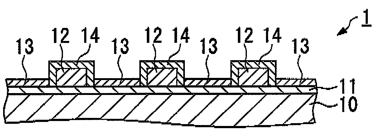
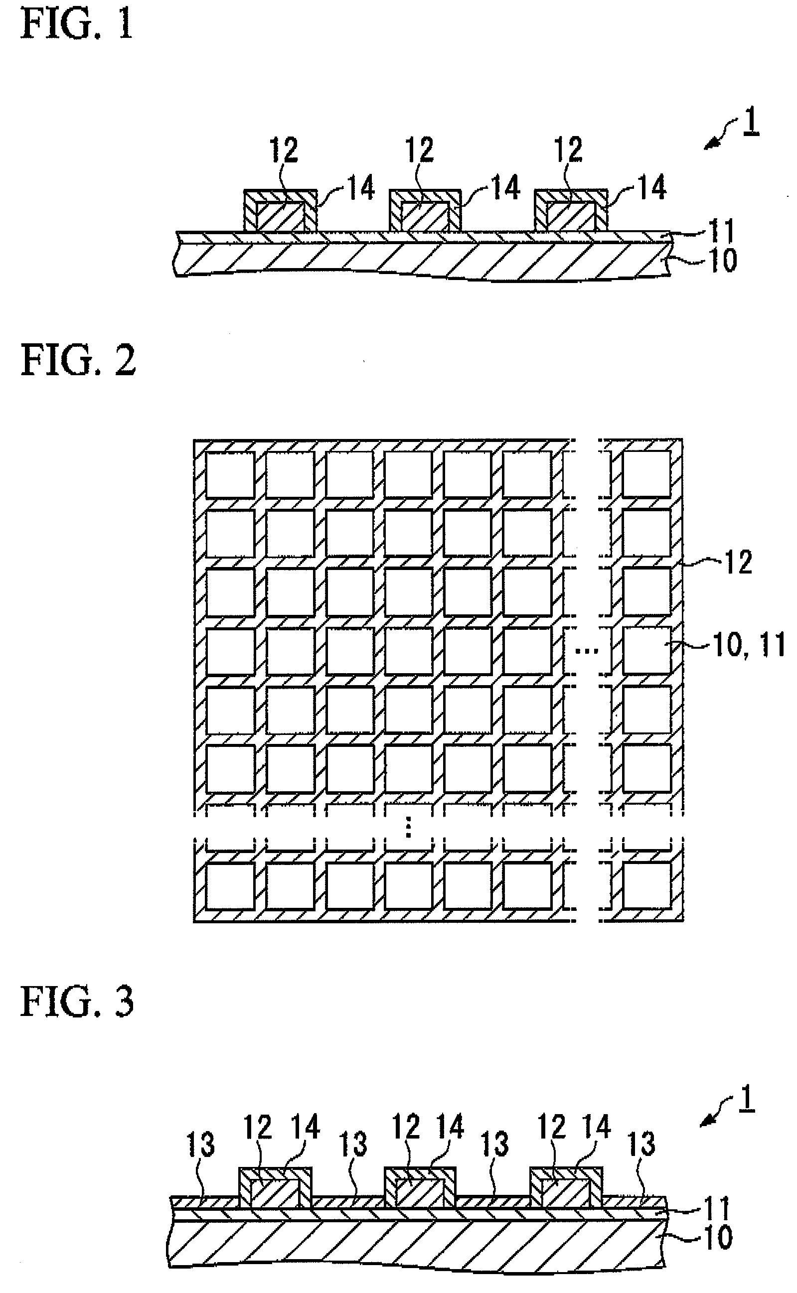
[0087]The electrode substrate shown in FIG. 1 was manufactured by the following procedure.

[0088]First, indium trichloride tetrahydrate and tin dichloride dihydrate are dissolved in ethanol to make a raw material solution for the ITO film. Also, a saturated water solution of ammonium fluoride was added and dissolved in an ethanol solution of tin tetrachloride pentahydrate to make a raw material solution for the FTO film. Next, the base substrate 10 made of glass A shown in Table 1 and having a dimension of 140 mm×140 mm and a thickness of 2.8 mm was placed on a heater plate to be heated. In this state, the raw material solution for the ITO film was sprayed on the base substrate 10 using a spray nozzle to form an ITO film with a film thickness of 800 nm, and then the raw material solution for the FTO film was sprayed on the base substrate 10 using a spray nozzle to form an FTO film with a film thickness of 200 nm, whereby the transparent conductive layer 11 which is a composite film o...

example 2 to example 11

[0091]The electrode substrates of Example 2 to Example 11 were obtained similarly to the electrode substrate 1 except for using a base substrate, an insulating layer and a sintering apparatus shown in Example 2 to Example 11 of Table 1 and adopting the heat treatment temperature shown in Example 2 to Example 11 of Table 1 (the top temperature keep time in the low-melting glass B was 15 minutes).

[0092]In each of Example 1 to Example 11, ten electrode substrates obtained in this manner were prepared, and, as shown below, the deformation of the base substrate 10, the cracking of the base substrate 10, and the density of the insulating layer 14 were investigated. The results are shown, in Table 2.

TABLE 2Example (ElectrodeSubstrate)Deformed (%)Cracked (%)Density100Good200Good300Good400Good500Good600Good700Good88020Good96040Good101000Good1100Bad

Deformation of the Base Substrate 10

[0093]The length of each of the four sides of the base substrate 10 is measured before and after the heat trea...

example 12

[0101]The electrode substrate of Example 12 was obtained similarly to the electrode substrate 1 except for using the base substrate shown in Example 12 of Table 1 and not providing the metal wiring layer 12 and the insulating layer 14.


PUM

PropertyMeasurementUnit
Temperatureaaaaaaaaaa
Strain pointaaaaaaaaaa

Abstract

The present invention relates to a method of manufacturing an electrode substrate that has a base substrate made of glass having a strain point of 520° C. or higher, a transparent conductive layer formed on the base substrate, a metal wiring layer, and an insulating layer made of low-melting glass that covers the metal wiring layer, the metal wiring layer and the insulating layer being provided on the transparent conductive layer, the method including at least the steps of providing paste that forms a base material of the low-melting glass so as to cover the metal wiring layer; and forming the insulating layer by sintering the paste by means of a heat treatment.

Description

TECHNICAL FIELD[0001]The present invention relates to an electrode substrate that is favorably used for a photoelectric conversion element or the like such as a dye-sensitized solar cell, and specifically relates to a method of manufacturing an electrode substrate that can reliably perform shielding of a metal wiring layer and has low resistance.[0002]Priority is claimed on Japanese Patent Application No. 2006-140258, filed May 19, 2006, the content of which is incorporated herein by reference.BACKGROUND ART[0003]Dye-sensitized solar cells, developed by the Swiss researcher Michael Graetzel, are a new type of solar cell attracting attention for their high photoelectric conversion efficiency and low manufacturing cost (for example, refer to Patent Document 1 and Non-Patent Document 1).[0004]A dye-sensitized solar cell is provided with: a working electrode having an oxide semiconductor porous film, on which a sensitizing dye made of oxide semiconductor fine particles is adsorbed, on a...

Claims


Application Information

Patent Timeline
IPC IPC(8): H01L31/00B32B3/10B05D3/02G01R19/00
CPCH01G9/2031H01G9/2059Y10T428/24917H01L51/445Y02E10/542H01G9/2068Y02P70/50H10K30/83H01L31/04
Inventor MATSUI, HIROSHI
Owner THE FUJIKURA CABLE WORKS LTD
Why Eureka
Try Eureka