
Belt welding apparatus and method

a welding apparatus and belt technology, applied in the field of belt welding apparatus and method, can solve the problems of cumbersome control of small belts, cumbersome hot melt techniques, and large wand heating means, and achieve the effects of easy control of the precise area of heat application, easy control of time of exposure, and difficult control

Active Publication Date: 2009-05-28
ACORS RONNIE B
View PDF11 Cites 12 Cited by
  • Summary
  • Abstract
  • Description
  • Claims
  • Application Information

AI Technical Summary

Benefits of technology

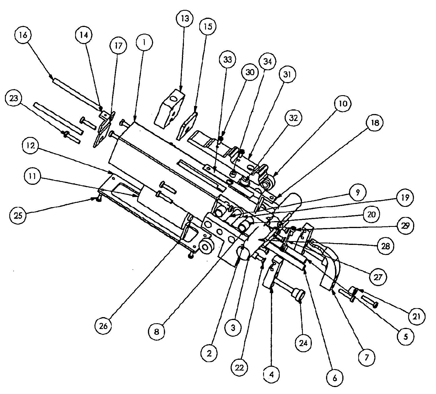
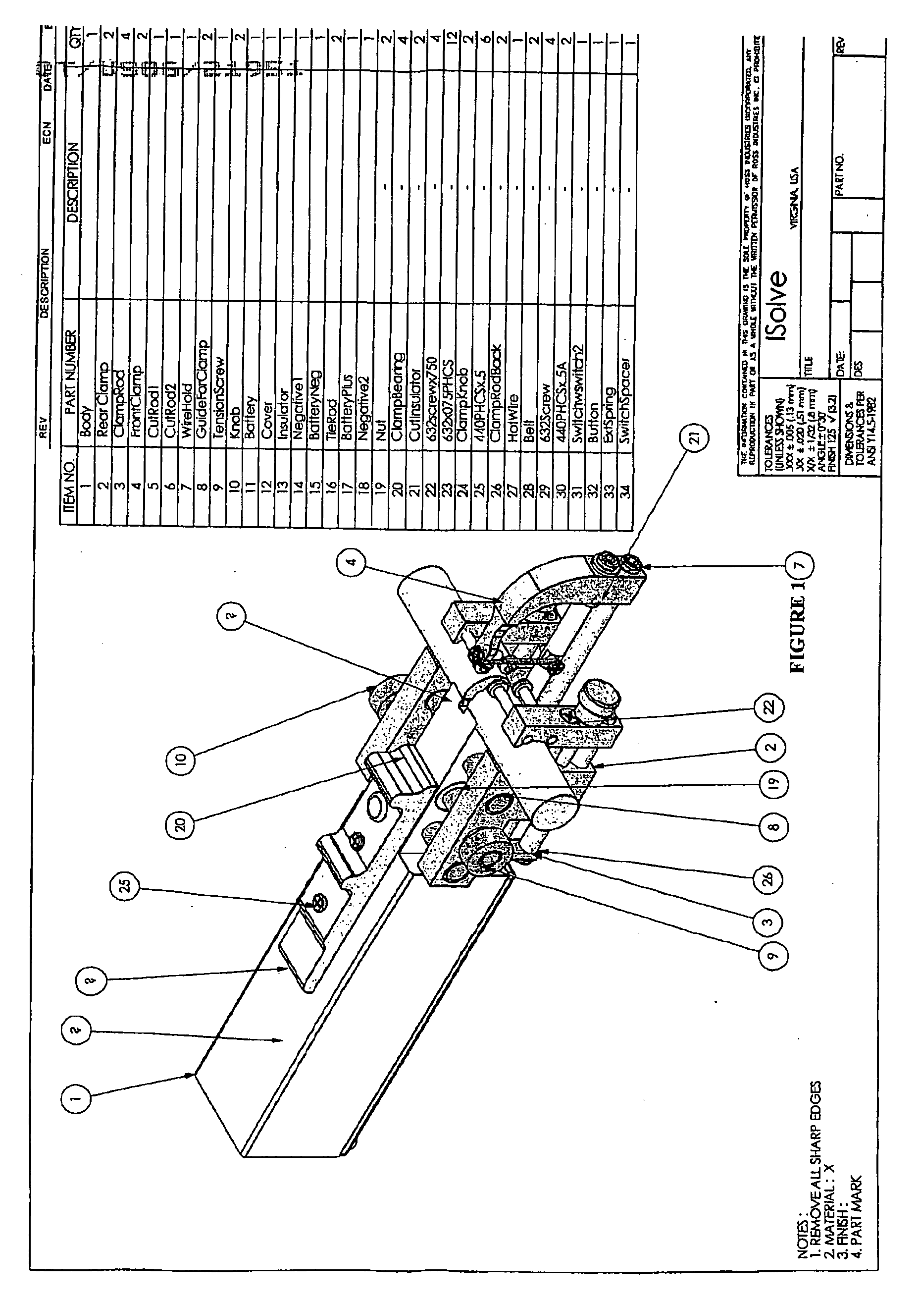
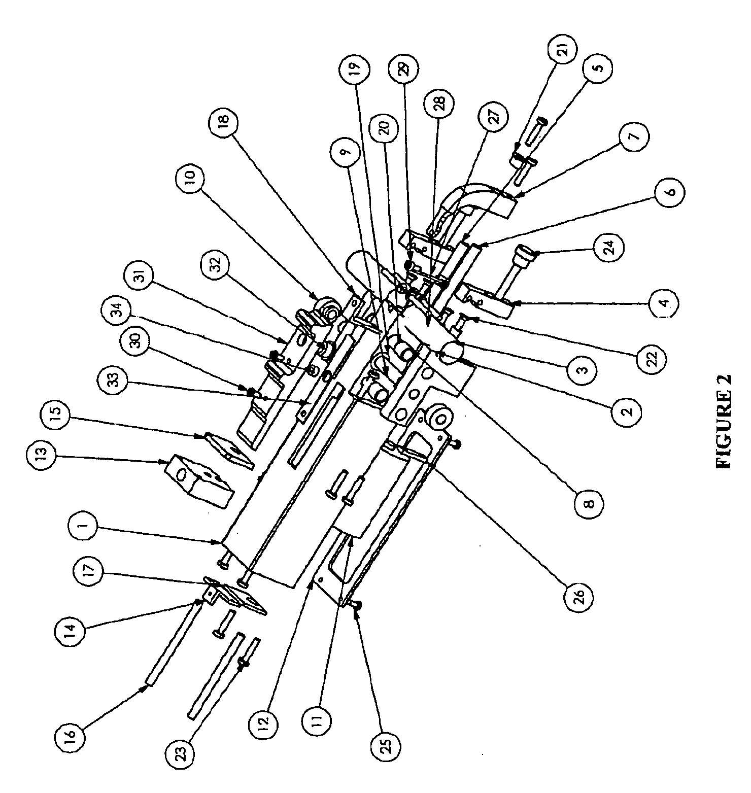
The present invention provides a device for joining thermoplastic material together with a compressive force while they are softened. This is accomplished by heating the material with a small hot wire and using clamps to securely press the ends together. The device is small and easy to control, and can be kept in a toolbox or handheld. The invention allows for precise heat application and reduces downtime from broken belts in manufacturing facilities. The speed of the heating process is controlled by the current and voltage passed through the wire, and the operator can easily inspect the molten state of the interface between the ends and join them with the hot wire.

Problems solved by technology

Both the conventional hot melt techniques, and large wand heating means, are cumbersome and difficult to control with small belts.

Method used


Image

  • Belt welding apparatus and method
  • Belt welding apparatus and method
  • Belt welding apparatus and method

Examples


example

[0042]Using any of the described embodiments and starting with a severed conventional polyurethane belt of ½ inch diameter the belt ends are securely fastened in the device in the manner described above. Using a 0.020 inch diameter ni-chrome wire and 1.2 volt D-cell battery, the wire is slowly advanced through the interface of the free ends. The belt is welded together such that the strength of the weld exceeded the service requirements of the belt, i.e. the belt could be fully tensioned within the service range.


PUM

PropertyMeasurementUnit
angleaaaaaaaaaa
angleaaaaaaaaaa
diameteraaaaaaaaaa

Abstract

Apparatus and method are disclosed for the welding of thermoplastic endless belts (28). Direct current is passed through a ni-chrome wire (27) to produce enough heat such that the thermoplastic melting point of the belt material is reached. The wire is mechanically moved through the abutting thermoplastic belt. The free ends being welded are securely held together with clamping members (2) and (4). In another embodiment a ni-chrome ribbon (54) is embedded in an electrically insulated screen to produce a heated planar surface. The invention is particularly suitable for the welding of polyurethane thermoplastic belts. Because the invention is hand held and it uses battery power, it is especially adapted for welding belts in the food processing industry.

Description

TECHNICAL FIELD[0001]This invention relates to a method of and an apparatus for splicing articles formed from a thermoplastic material, such as an endless belt, conveyor belt, or handrail for an escalator. The invention particularly relates to a method and apparatus for splicing polyurethane thermoplastic endless belts. However, it is to be understood that the invention can be used to weld any thermoplastic stock material of a myriad of cross-sectional shapes.BACKGROUND ART[0002]Endless belts made from entirely thermoplastic, or fabric reinforced composite belts with thermoplastic ends for splicing, are well known in the art. Handrails such as those used with escalators also utilize an endless belt that is known to be spliced onto itself through thermoplastic welding. See for instance, U.S. Pat. No. 6,086,806 to Weatherall, et al., where a heated mandrel and a T-shaped mold are used to melt thermoplastic terminal portions of an endless belt. The melted ends of the thermoplastic mate...

Claims


Application Information

Patent Timeline
Patent Type & Authority Applications(United States)
IPC IPC(8): B29C65/30B30B5/00
CPCB29C65/2061Y10T156/18B29C65/7841B29C66/1142B29C66/52211B29C66/5241B29C66/73921B29C66/80B29C66/855B29C66/861B29C66/8618B29L2031/7092B29L2031/7094F16G3/003B29C65/222B29C65/224B29C65/2046B29C65/7802B29C66/81871B29C66/81875
Inventor ACORS, RONNIE B.
Owner ACORS RONNIE B
Learn More