Joint structure of copper wire and aluminum wire, and joint method

Inactive Publication Date: 2009-05-28
YAZAKI CORP
View PDF2 Cites 16 Cited by
  • Summary
  • Abstract
  • Description
  • Claims
  • Application Information

AI Technical Summary

Benefits of technology

[0033]According to the invention, it is possible to enhance the fixing force of the electric wires by caulking with the joint terminal, and at the same time, the electrically favorable connection can

Problems solved by technology

Since it has been difficult to use aluminum wires which are inferior in property such as electrical conductivity, strength, etc.
However, in recent years, use of the aluminum wires has been more and more required in consideration of weight reduction of the vehicle, a resulting low fuel cost, and recycling performance.
For example, it is a main stream that the known electric component such as a connector is produced on t

Method used


Image

  • Joint structure of copper wire and aluminum wire, and joint method
  • Joint structure of copper wire and aluminum wire, and joint method

Examples


Example

[0038]Now, a preferred embodiment according to the invention will be described in detail referring to the drawings.

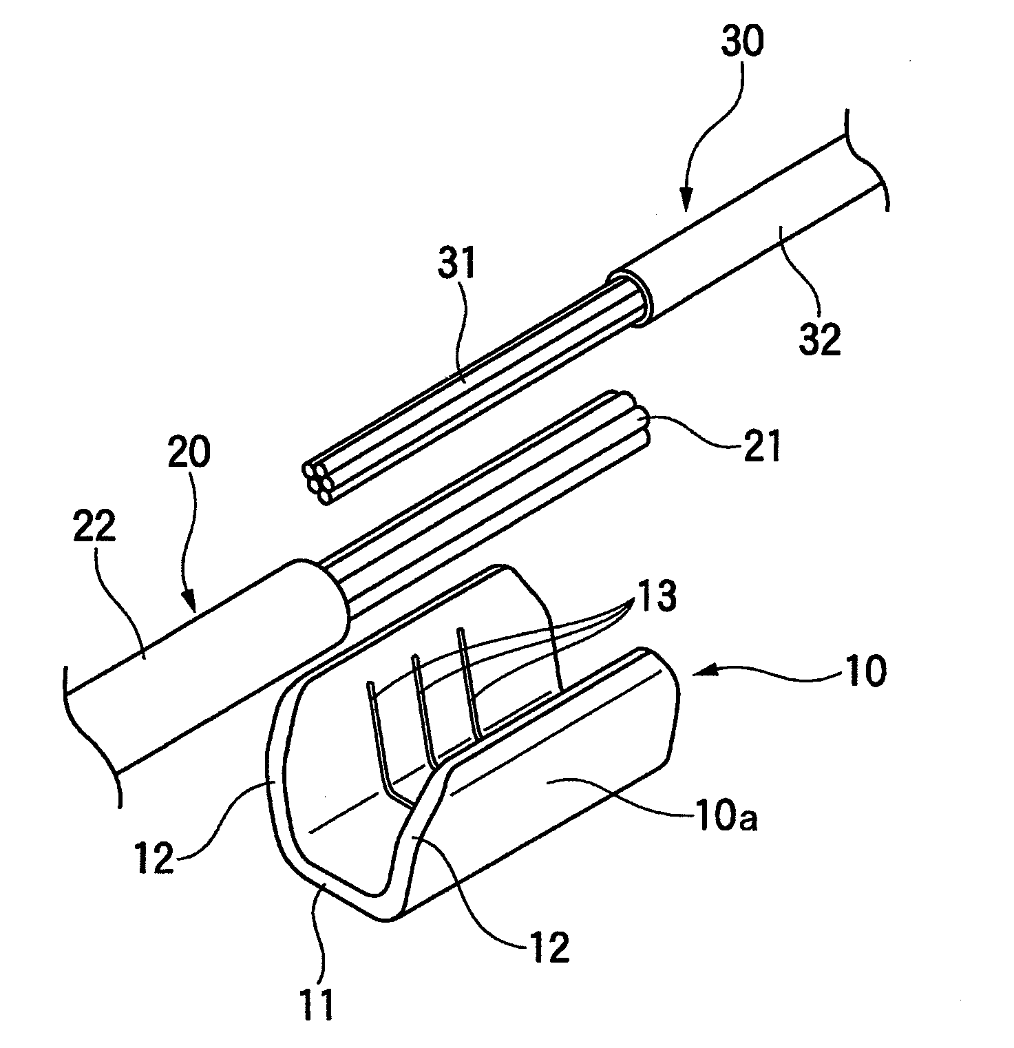
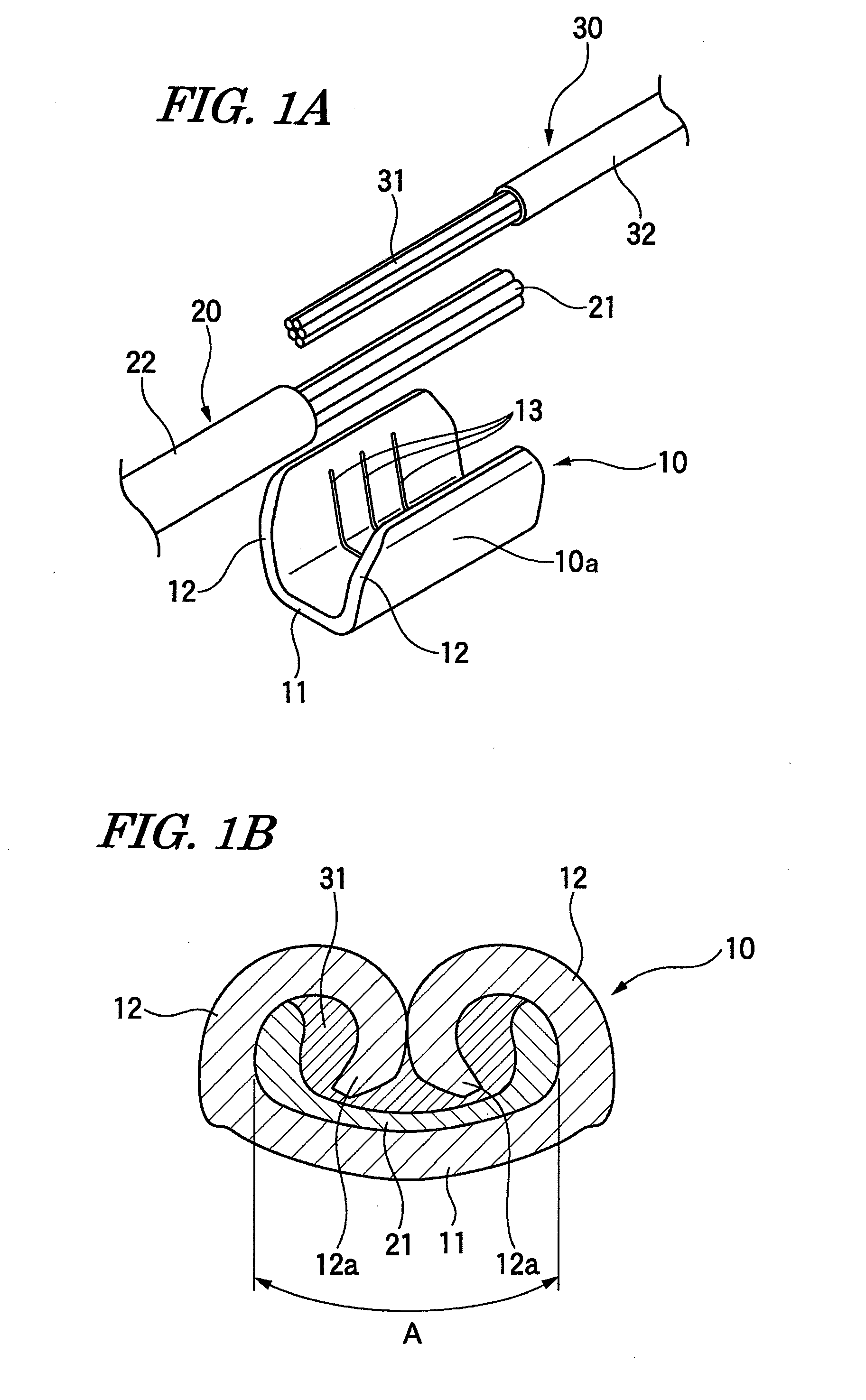
[0039]FIGS. 1A and 1B are explanatory views of a joint structure and a joint method in the embodiment, in which FIG. 1A is a view showing a state of setting an aluminum wire and a copper wire in a joint terminal, and FIG. 1B is a sectional view of a joint part after caulked.

[0040]A joint terminal 10 used in this embodiment is a terminal provided with a conductor press-fitting part 10a having a U-shape in cross section, which includes a bottom plate 11 and a pair of conductor caulking pieces 12 which are upwardly extended from both side edges of the bottom plate 11, and is inwardly folded to caulk the conductors in tight contact with an upper face of the bottom plate 11 so as to enclose conductors of the electric wires to be connected. Three serrations (that is, shallow grooves formed by stamping) extending in a direction perpendicular to a longitudinal direction of the ...


PUM

PropertyMeasurementUnit
Diameteraaaaaaaaaa

Abstract

A joint structure of electric wires includes: a copper wire which includes a conductor formed of copper; an aluminum wire which includes a conductor formed of aluminum or aluminum alloy; and a joint terminal provided with a conductor press-fitting part having a U-shape in cross section. The conductor press-fitting part includes a bottom plate and a pair of conductor caulking pieces which are upwardly extended from both side edges of the bottom plate, and is inwardly folded to caulk the conductors of the copper wires and the aluminum wires so as to enclose the conductors. The conductor press-fitting part is press-fitted to the conductors of the aluminum wire and the copper wire in a state that the conductor of the aluminum wire is disposed on the upper face of the bottom plate, and the conductor of the copper wire is disposed on the conductor of the aluminum wire.

Description

BACKGROUND OF THE INVENTION[0001]1. Technical Field[0002]The present invention relates to a joint structure in which a copper wire and an aluminum wire are electrically connected to each other by means of a joint terminal, and a joint method for obtaining the joint structure.[0003]2. Background Art[0004]The joint terminal has been used for direct connection between electric wires (For example, see JP-A-9-180848). The joint terminal is a terminal having a U-shape in cross section, which includes a bottom plate, and a pair of conductor caulking pieces provided upright at both side edges of the bottom plate and adapted to be folded inwardly so as to enclose conductors of the electric wires to be connected thereby to caulk the conductors in tight contact with an upper face of the bottom plate.[0005]In case of connecting two covered wires by means of this joint terminal, two conductors (each of the conductors includes a bundle of a plurality of raw wires in a form of twisted wires) which...

Claims


Application Information

Patent Timeline
IPC IPC(8): H01R4/18H01R43/048
CPCH01R4/20Y10T29/49194H01R13/03H01R4/62
Inventor ONUMA, MASANORI
Owner YAZAKI CORP
Why Eureka
Try Eureka