Edge-on SAR scintillator devices and systems for enhanced spect, pet, and compton gamma cameras

a scintillator and sar technology, applied in the field of enhanced spect, pet, compton gamma cameras, can solve the problems of non-directional emission of photons from the radionuclide source distribution, affecting the resolution of the sar, and the distribution of radiation sources itself is typically not well-defined, so as to reduce the noise of the photodetector and minimize the dead space. , the effect of improving the resolution

Inactive Publication Date: 2009-05-28
MINNESOTA IMAGING & ENG
View PDF26 Cites 84 Cited by
  • Summary
  • Abstract
  • Description
  • Claims
  • Application Information

AI Technical Summary

Benefits of technology

[0020]In accordance with the present invention, an edge-on scintillator detector module with SAR capability is provided as a radiation detection device for nuclear medicine (SPECT, PET, Compton camera) imaging. Specific implementations can be used for SPECT-PET imaging and hand-held SPECT or PET camera imaging, including probes. The edge-on SAR scintillator detector module can be used to detect both particle and photon radiation, making it suitable for other applications such as radiation therapy portal imaging, nuclear remediation, mine detection, container inspection, and high energy physics and astronomy. Two main implementations of the edge-on SAR scintillator detector module use either scintillator rods or scintillator blocks. Two categories of scintillator blocks include 3-D and 2-D (sheet) blocks. Trade-offs exist in terms of cost of implementation, spatial and energy resolution, response uniformity, dead detector volume, and detector dead time. Scintillator rods and blocks can both be incorporated into an edge-on SAR scintillator detector module. A number of external (surface) and internal optimization techniques (encoding methods) are described that can result in improved SAR resolution. Multiple scintillator materials as well as non-scintillator materials can be incorporated into an edge-on SAR scintillator detector module. A variety of photodetector readout systems can be coupled to an edge-on SAR scintillator detector module. Two exemplary readout formats are one-side and multi-side (typically two-side) readout. Exemplary photodetector geometries include 2-D arrays, 1-D strip arrays, and position-sensitive area detectors. Modifications to these photodetector geometries may reduce photodetector readout noise as well as edge-on SAR scintillator detector dead time. Thin photodetector devices can be used to minimize the dead space between detector modules.

Problems solved by technology

Image data acquisition in nuclear medicine presents several challenges in addition to constraints imposed by finite acquisition times and patient exposure restrictions.
Unfortunately, the emission of photons from the radionuclide source distribution is non-directional and the radiation source distribution itself is typically not well-defined.
Imaging systems typically offer poor directional discrimination capability and have finite response times within which to detect events (thereby limiting detection rates).
It provides a limited degree of spatial resolution and energy resolution while removing some fraction of scattered radiation that would otherwise degrade image quality.
Unfortunately a substantial fraction of useful unscattered radiation is also attenuated.
Drawbacks to employing 2-D CdZnTe arrays capable of high detection efficiency include the difficulty of growing thick CdZnTe crystals with acceptable levels of defects and creating low noise, 2-D array readout structures on CdZnTe crystals.
A limitation of the face-on detection format for SPECT and PET imaging is that properties such as the detection efficiency, spatial resolution, and energy resolution exhibit a noticeable energy dependence.
The problem of dead space between basic edge-on detector planes is more severe for basic edge-on scintillator array detectors than for basic edge-on semiconductor array detectors.
This dead space degrades the spatial resolution in one dimension as well as the detection efficiency.

Method used


Image

  • Edge-on SAR scintillator devices and systems for enhanced spect, pet, and compton gamma cameras
  • Edge-on SAR scintillator devices and systems for enhanced spect, pet, and compton gamma cameras
  • Edge-on SAR scintillator devices and systems for enhanced spect, pet, and compton gamma cameras

Examples


Embodiment Construction

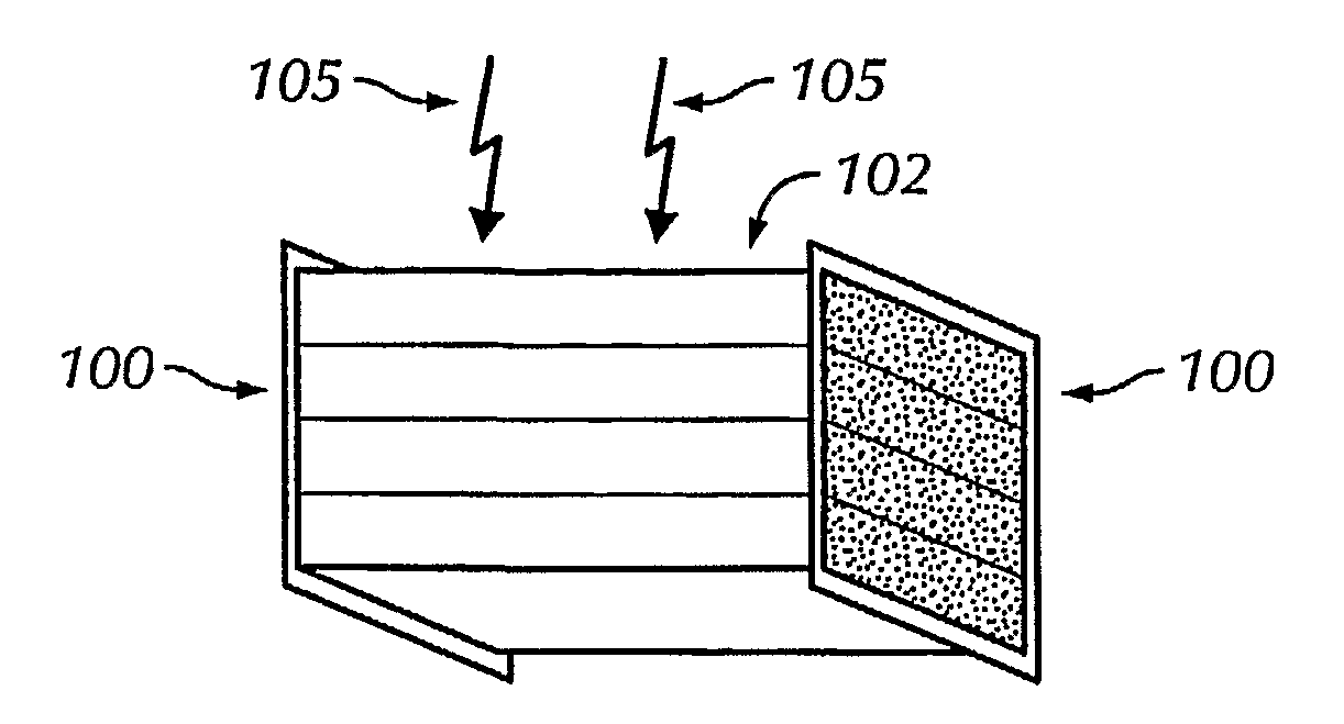
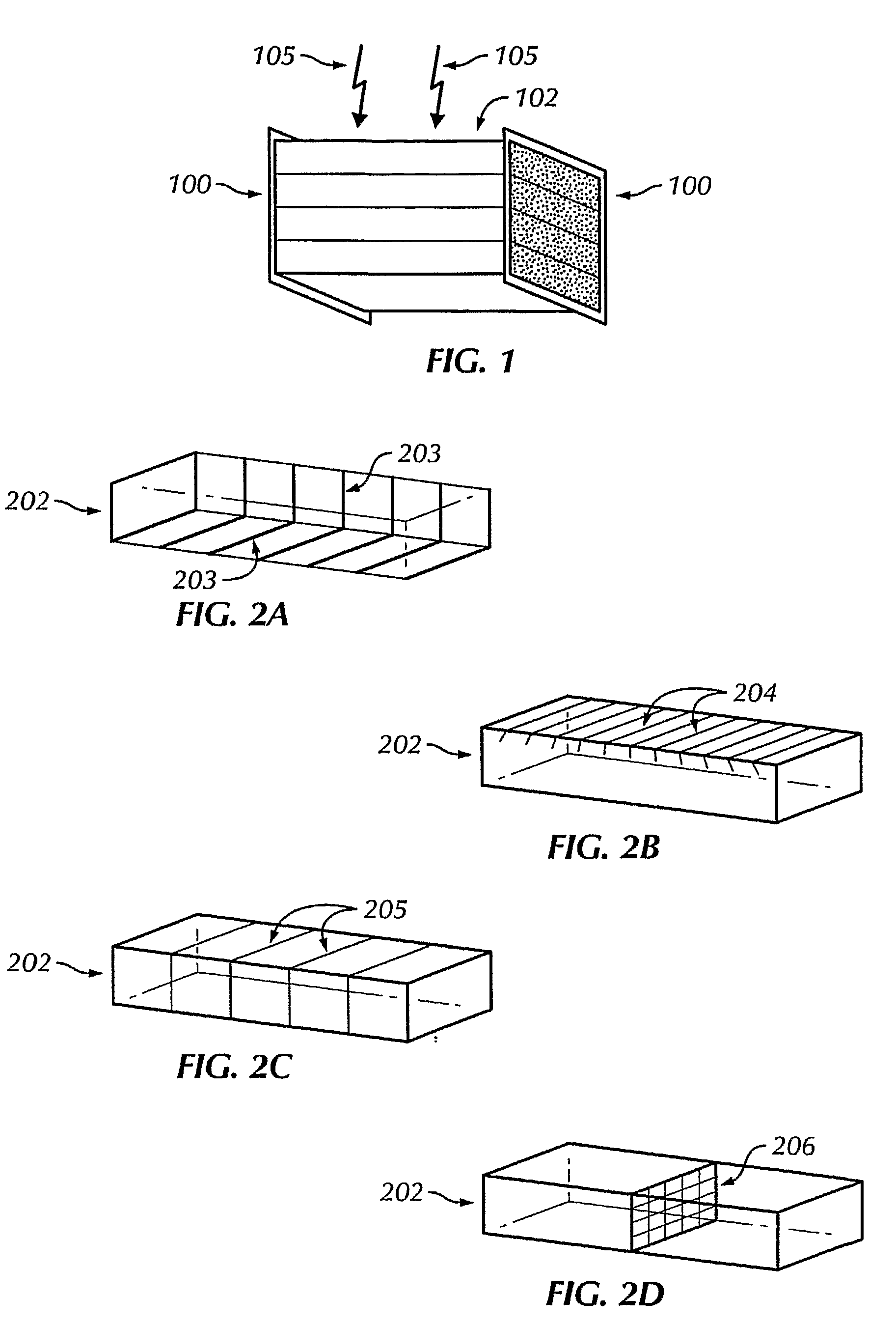
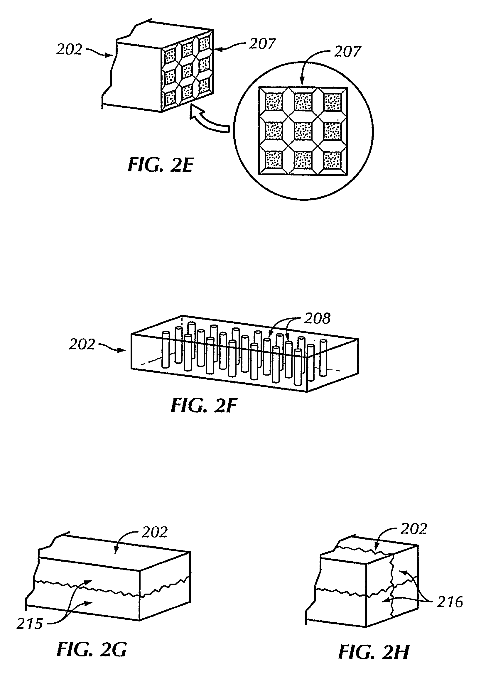
[0091]The invention provides designs for edge-on scintillator rod and block detectors with SAR capability, as well as readout devices, which are incorporated into discrete detector modules that can be used for radiation imaging directly, for small hand-held imaging devices, and / or as part of a detector module array. Edge-on SAR scintillator rod and block detectors typically implement one-side or two-side readout designs. Planar and ring detector geometries are widely used in nuclear medicine. Arrays of edge-on SAR detector modules can be assembled to form planar and ring detectors. The general properties of an edge-on detector module (comprised of edge-on scintillator and semiconductor detectors, readout and processing electronics, power management, communications, temperature control, and radiation shielding) as well as several edge-on detector module array configurations are described in Nelson, U.S. Pat. No. 6,583,420 and Nelson, U.S. Pat. Appl. publication No. 20040251419, and N...


PUM


Abstract

The invention provides methods and apparatus for detecting radiation including x-ray, gamma ray, and particle radiation for nuclear medicine, radiopaphic imaging, material composition analysis, high energy physics, container inspection, mine detection and astronomy. The invention provides detection systems employing one or more detector modules (102) comprising edge-on scintillator detectors (101) with sub-aperture resolution (SAR) capability employed, e.g., in nuclear medicine, such as radiation therapy portal imaging, nuclear remediation, mine detection, container inspection, and high energy physics and astronomy. The invention also provides edge-on imaging probe detectors for use in nuclear medicine, such as radiation therapy portal imaging, or for use in nuclear remediation, mine detection, container inspection, and high energy physics and astronomy.

Description

FIELD OF THE INVENTION[0001]This invention provides novel edge-on sub-aperture resolution (SAR) scintillator detectors, designs and systems for, e.g., enhanced single photon emission computed tomography (SPECT) and positron emission tomography (PET), and Compton gamma cameras employed in nuclear medicine, such as radiation therapy portal imaging, and for nuclear remediation, mine detection, container inspection, and high energy physics and astronomy. The invention also provides edge-on imaging probe detectors for use in nuclear medicine, such as radiation therapy portal imaging, or for use in nuclear remediation, mine detection, container inspection, and high energy physics and astronomy.BACKGROUND OF THE INVENTION[0002]Two important imaging modalities in nuclear medicine are single photon emission computed tomography (SPECT) and positron emission tomography (PET) in which a fraction of the photons emitted directly or indirectly (through positron annihilation) by a radionuclide dist...

Claims


Application Information

Patent Timeline
Patent Type & Authority Applications(United States)
IPC IPC(8): G01T1/20
CPCG01T1/202G01T1/2002G01T1/2008
Inventor NELSON, ROBERT SIGURD
Owner MINNESOTA IMAGING & ENG
Why Eureka
Try Eureka