Electric power conversion system
- Summary
- Abstract
- Description
- Claims
- Application Information
AI Technical Summary
Benefits of technology
Problems solved by technology
Method used
Image
Examples
first embodiment
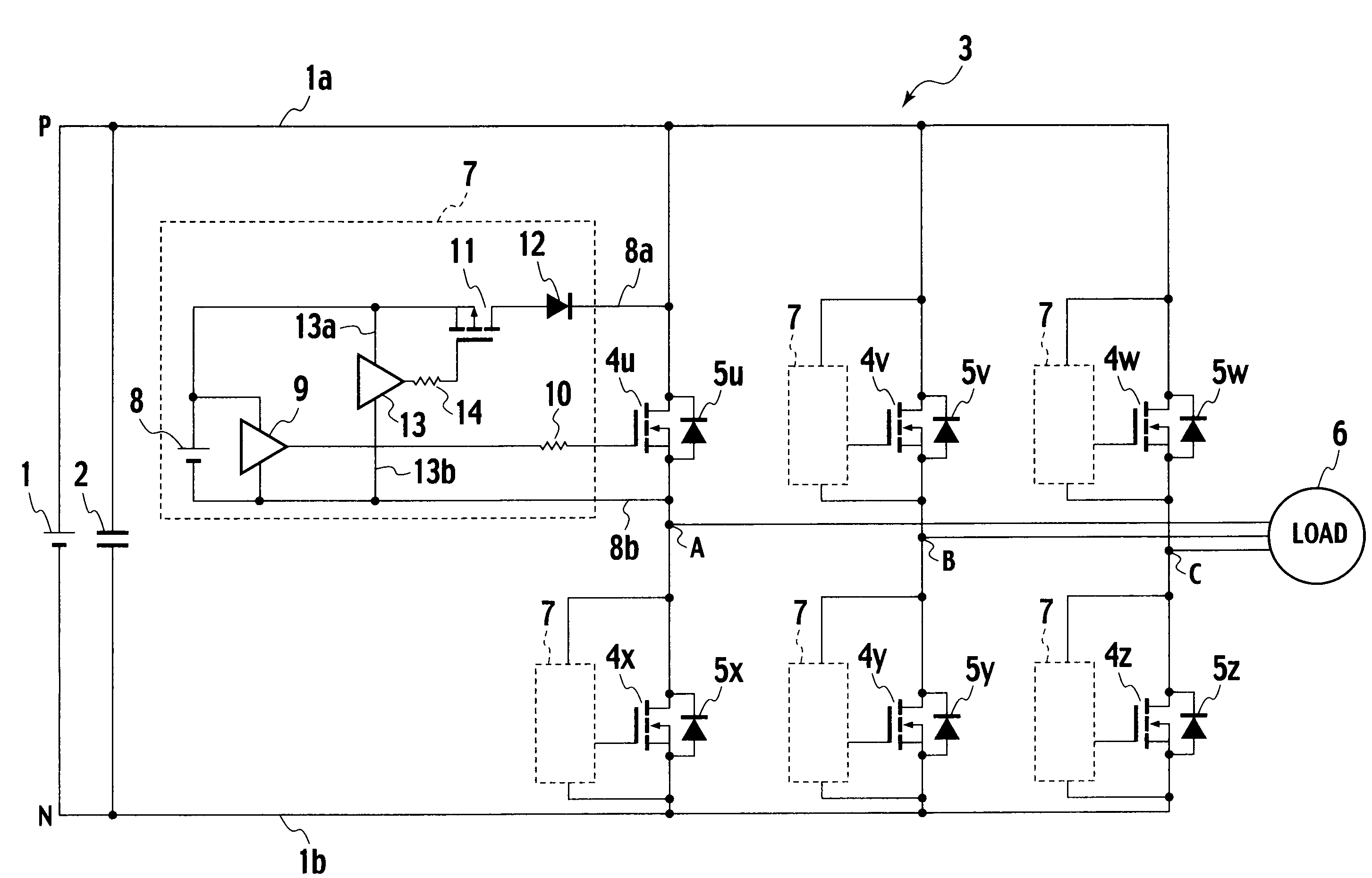
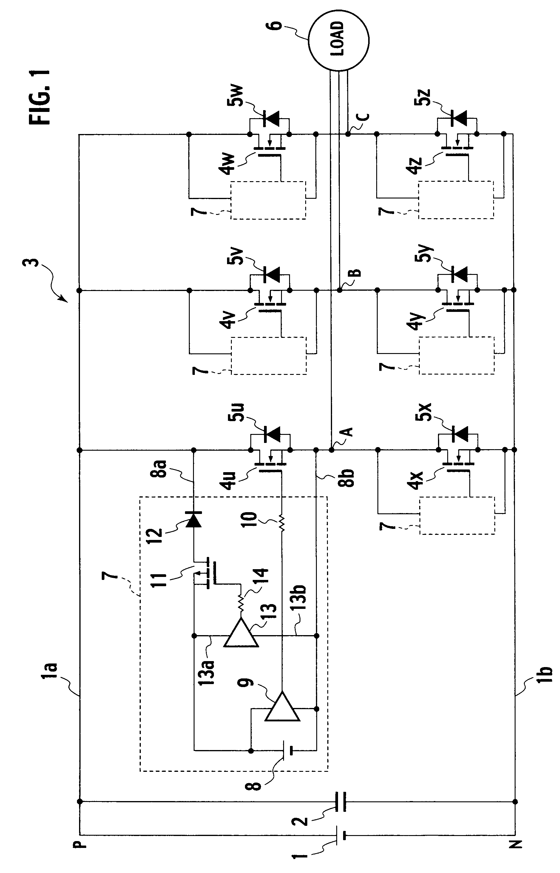
[0019]FIG. 1 is a circuit configuration diagram of an electric power conversion system according to the first embodiment of the present invention. In FIG. 1, a direct current voltage source 1 is implemented as a rectified three-phase alternating current power supply, for example; and as well as a smoothing capacitor 2, an inverter main circuit 3 is connected between a positive direct current bus 1a and a negative direct current bus 1b of the direct current voltage source 1. The inverter main circuit 3 is configured in the form of three-phase bridge connections of main circuit switching devices 4u, 4v, and 4w corresponding to main circuit switching devices of positive arms and main circuit switching devices 4x, 4y, and 4z of negative arms. Those main circuit switching devices 4u, 4v, 4w, 4x, 4y, and 4z have free wheeling diodes 5u, 5v, 5w, 5x, 5y, and 5z reverse parallel connected between positive electrodes and negative electrodes thereof, respectively. Further, the inverter main ci...
second embodiment
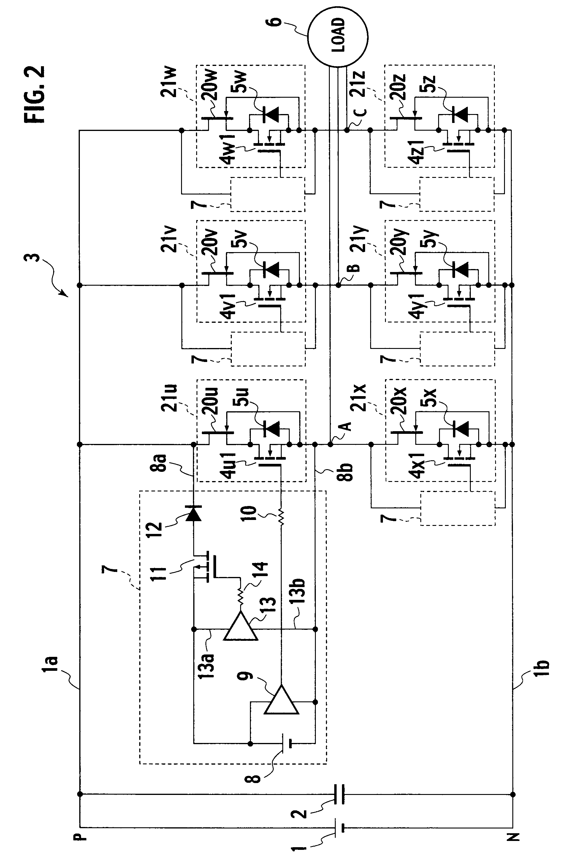
[0029]FIG. 2 is a circuit configuration diagram of an electric power conversion system according to the second embodiment of the present invention. As of parts of this embodiment, like parts to parts of the circuit configuration diagram of the electric power conversion system according to the first embodiment shown in FIG. 1 are designated by like reference characters, and description thereof is omitted. The present embodiment is different from the first embodiment in that it is configured such that main circuit switching devices 4u1, 4v1, 4w1, 4x1, 4y1, and 4z1 are low withstand-voltage devices, and those devices have at positive electrode ends thereof normally on switching devices 20u, 20v, 20w, 20x, 20y, and 20z inserted in series to those devices, respectively, the normally on switching devices 20u, 20v, 20w, 20x, 20y, and 20z having gates thereof connected to negative electrodes of the main circuit switching devices 4u, 4v, 4w, 4x, 4y, and 4z, respectively.
[0030]In a main circu...
third embodiment
[0038]FIG. 3 is a circuit configuration diagram of an electric power conversion system according to the third embodiment of the present invention. As of parts of this embodiment, like parts to parts of the circuit configuration diagram of the electric power conversion system according to the second embodiment shown in FIG. 2 are designated by like reference characters, and description thereof is omitted. The present embodiment is different from the second embodiment in that a current limiting resistor 15 is inserted at a positive electrode end of a low-voltage direct current power supply 8 of a reverse voltage application circuit 7A, and a high-frequency capacitor 16 is provided between the current limiting resistor 15 and a negative electrode of the low-voltage direct current power supply 8.
[0039]The low-voltage direct current power supply 8 has a voltage selected to one fourth of a voltage of a direct current voltage source 1, and the high-frequency capacitor 16 should not be any ...
PUM
 Abstract
Description
Claims
Application Information
 - R&D
- Intellectual Property
- Life Sciences
- Materials
- Tech Scout
- Unparalleled Data Quality
- Higher Quality Content
- 60% Fewer Hallucinations
Browse by: Latest US Patents, China's latest patents, Technical Efficacy Thesaurus, Application Domain, Technology Topic, Popular Technical Reports.
© 2025 PatSnap. All rights reserved.Legal|Privacy policy|Modern Slavery Act Transparency Statement|Sitemap|About US| Contact US: help@patsnap.com


