Air-Conditioning System

a technology of air-conditioning system and air-conditioning system, which is applied in the direction of heating types, instruments, and static/dynamic balance measurement, etc., can solve the problems that the central control apparatus cannot effectively manage the units or the room temperature adjustment, and achieve the effect of reducing traffic, avoiding heavy traffic, and reducing traffic over the first transmission lin

Inactive Publication Date: 2009-06-04
MITSUBISHI ELECTRIC CORP
View PDF3 Cites 36 Cited by
  • Summary
  • Abstract
  • Description
  • Claims
  • Application Information

AI Technical Summary

Benefits of technology

[0009]According to the present invention, since the arithmetic processing means for performing data processing is provided in the transmission relay and the arithmetic processing means is configured to process the data included in the signal transmitted from the connected second transmission means, the transmission relay performs all of or part of operations for processing various data that the centralized control apparatus performs. With this configuration, it is possible to reduce the traffic between each of the indoor units and the centralized control apparatus. Accordingly, the traffic over the first transmission line is reduced in comparison with a conventional system and heavy traffic can be avoided. In addition, each of the plurality of transmission relays processes the data, whereby the processing load can be distributed and the load of the processing that the centralized control apparatus performs can be reduced.

Problems solved by technology

For this reason, for example, the centralized control apparatus cannot perform an effective management on the units or the room temperature adjustment.

Method used


Image

  • Air-Conditioning System
  • Air-Conditioning System
  • Air-Conditioning System

Examples


embodiment 2

[0040]In the above-described embodiment 1, the operation for collecting data regarding the used electric power that the transmission relay 400 performs has been described. The monitoring operation that the centralized control apparatus 300 performs employing the polling method is not limited to that on the data regarding the used electric power. For example, the polling method is also employed in an operation for monitoring occurrence of an abnormality in the indoor units 200. In this embodiment, an example of an operation for monitoring occurrence of an abnormality will be described. The system configuration or the like is the same as that described in the embodiment 1, thus description thereof is omitted.

[0041]A data processing unit 430B causes second transmission means 420 to transmit a request signal for abnormality determination. In an indoor unit 200 that has received the request signal by indoor unit communication means 220, indoor unit controlling means 210 performs a detect...

embodiment 3

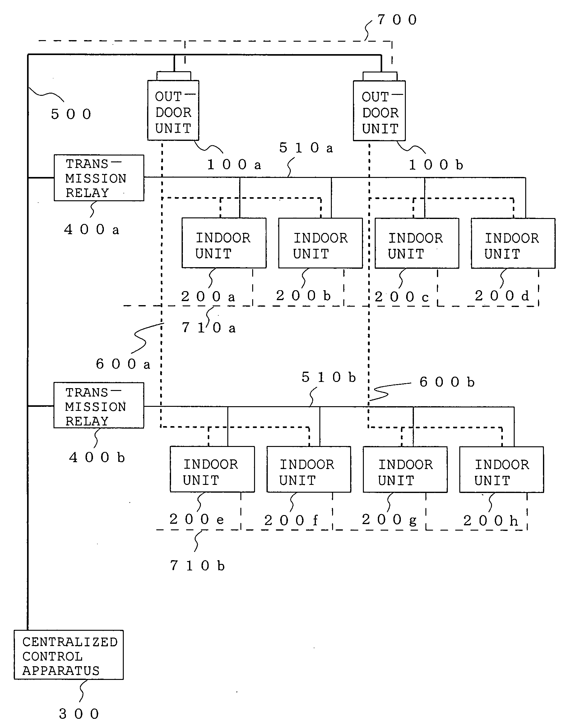
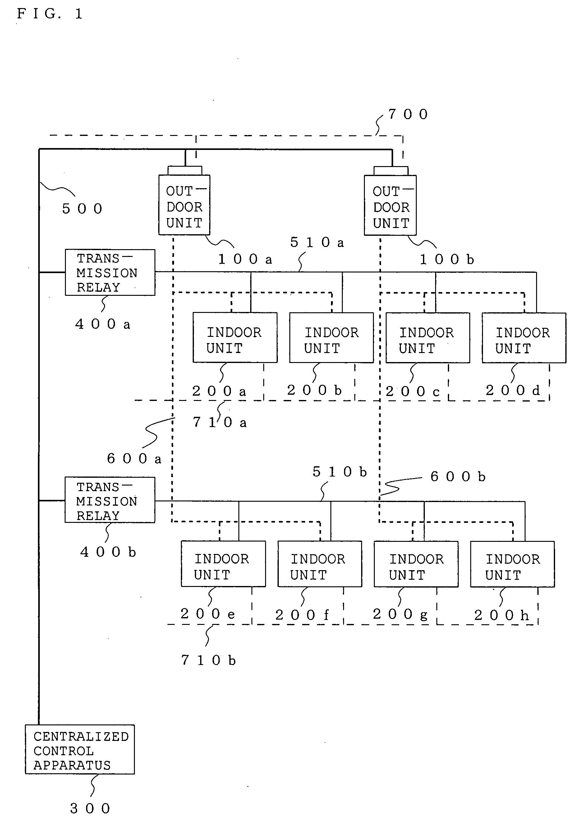
[0045]FIG. 7 is a diagram showing a configuration of an air-conditioning system according to an embodiment 3 of the present invention. This embodiment differs from the above-described embodiments in that power lines 720 (720a and 720b) capable of transmitting signal like the second transmission lines 510 are used instead of the power lines 710 for supplying electric power to each indoor unit 200.

[0046]In the air-conditioning systems according to the above-described embodiments, the second transmission lines 510 and the power lines 710 are constituted by different lines. In this embodiment, a necessity of wiring with a dedicated communication line is eliminated and a wiring cost can be reduced by configuring the power lines 720 to carry signals instead of the second transmission lines 510.

[0047]Methods for transmitting signals over the power line are not specified in particular. For example, to increase the noise resistance, communication employing a spread spectrum method may be per...

embodiment 4

[0048]FIG. 8 is a diagram showing a configuration of an air-conditioning system according to an embodiment 4 of the present invention. In this embodiment, communication is performed via radio waves (wireless) instead of the second transmission lines 510 used in the above-described embodiments. The communication method is not specified in particular. However, in this example, it is assumed that ZigBee (ZigBee is a registered trademark of Koninklijke Philips Electronics NV. hereinafter, simply referred to as ZigBee) is used as the radio communication method.

[0049]In this embodiment, radio wave communication means 290 (290a to 290h) and radio wave communication means 450 (450a and 450b) are provided in the indoor units 200 and the transmission relays 400 instead of the indoor unit communication means 220 and the second transmission means 420, respectively. In addition, this embodiment differs from the above-described embodiments in that the second transmission lines 510 are not arrange...


PUM


Abstract

An air-conditioning system capable of reducing traffic of signals and effectively performing control and management operations without causing heavy traffic is obtained. In an air-conditioning system including one or more indoor units 200, one or more outdoor units 100, and a centralized control apparatus 300 and performing signal communication, a transmission relay 400 is provided between a first transmission line 500 to which the one or more outdoor units 100 and the centralized control apparatus 300 are connected and a second transmission line 510 to which one or more indoor units 200 constituting a group are connected, the transmission relay 400 relays a signal between the first transmission line 500 and the connected second transmission line 510. The transmission relay 400 further includes arithmetic processing means 430 for processing data included in the signal transmitted via the connected second transmission line 510, and data storage means 440 for storing data regarding the processing by the arithmetic processing means 430.

Description

TECHNICAL FIELD[0001]The present invention relates to an air-conditioning system that controls indoor units and outdoor units with a centralized control apparatus. In particular, the present invention relates to communication of signals including data among the indoor units, the outdoor units, and the centralized control apparatus.BACKGROUND ART[0002]For example, in the architecture such as buildings, there are air-conditioning systems configured to control a plurality of indoor units, each of which is installed indoors and adjust the room temperature to an instructed temperature, and a plurality of outdoor units, each of which is installed outdoors and exhaust heat, with a centralized control apparatus. At this time, the outdoor units, the indoor units, and the centralized control apparatus are connected by transmission lines or the like to constitute a network. For example, each of the units or the apparatus transmits various signals including control data such as (operation on / of...

Claims


Application Information

Patent Timeline
Patent Type & Authority Applications(United States)
IPC IPC(8): F25B49/00
CPCF24F11/0009F25B13/00F24F2011/0068F24F2011/0067F24F11/30F24F11/54F24F11/56F24F11/52F24F11/84F24F11/64F24F11/38
Inventor MASUI, HIROTAKA
Owner MITSUBISHI ELECTRIC CORP
Why Eureka
Try Eureka