Fan cooling unit for cooling electronic components

a technology of electronic components and cooling units, which is applied in the direction of electrical apparatus construction details, separation processes, filtration separation, etc., can solve the problems that the overall permeability of the filter media is substantially affected by the layer, and achieves the effect of preventing corrosion of electronic components, high salt retention, and long li

Inactive Publication Date: 2009-06-04
SCHWARZ ROBERT +3
View PDF32 Cites 29 Cited by
  • Summary
  • Abstract
  • Description
  • Claims
  • Application Information

AI Technical Summary

Benefits of technology

[0006]The depth filtration media layer preferably comprises fibers having an electrostatic charge, which charge is not so strong as to affect the electronic components in the casing. While electrically charged filter material may be made by a variety of known techniques, one convenient way of cold charging the fiber web is described in U.S. Pat. No. 5,401,446. The charged fibers enhance filter performance by attracting small particles to the fibers and retaining them. It has been found that the pressure drop in the filter media thereby increases at a slower rate than it does without the electrical charge in the depth filtration media.
[0015]Due to the multilayer structure of the composite filter media, only some very small air particles will penetrate the depth filtration media prefilter and will reach the membrane surface with a certain delay. The melt blown prefilter with a filtration efficiency of about 90%, thus, already filters a major part of the particles. Over the time a filter cake builds up on the upstream side of the prefilter. Such filter cake provides an additional filtering effect. The filter cake's filtering efficiency enhances over the time and constitutes a kind of pre-prefilter. When a filter loaded in the aforementioned manner is exposed to a humid climate with e.g. more than 90% relative humidity, the filter cake exhibits an important function for the entire filter media. More particularly, if the filter cake was built up directly on the surface of the membrane material, swelling of the filter cake particles in humid climate would result in an increased pressure drop over the filter media. However, such pressure drop increase is less if the filter cake is separated from the membrane surface such as by means of the prefilter.

Problems solved by technology

It is to be noted, however, that the support layer will substantially affect the overall permeability of the filter media.

Method used


Image

  • Fan cooling unit for cooling electronic components
  • Fan cooling unit for cooling electronic components
  • Fan cooling unit for cooling electronic components

Examples


example 1

[0061]A layer of 10 g / m2 melt blown media (DelPore 6001-10P, available from DelStar, Inc.; Middletown, Del.) are placed upstream of the ePTFE membrane laminate of comparative example 1 to form a composite media. The melt blown media is made of 10 g / m2 polypropylene meltblown layer and 10 g / m2 polyester spunbond scrim. The polypropylene fibers have diameters of from 1 to 5 μm. The mean pore size is about 15 μm and the media thickness is about 0.2 mm. The air permeability of the depth filtration layer is about 130 Frazier. The media is electrically charged to enhance particle collection efficiency. The filter is loaded with sodium chloride aerosol in accordance with the test procedure described previously until pressure drop reaches 750 Pa. The loading curve is depicted in FIG. 6.

example 2

[0062]A depth filtration media layer of 30 g / m2 melt blown media (DelPore 6001-30P, available from DelStar, Inc.; Middletown, Del.) is positioned upstream of the microporous ePTFE laminate of Comparative Example 1 to form a composite media. The melt blown media is made of 30 g / m2 polypropylene fibers layer and 10 g / m2 polyester spun bond scrim. The polypropylene fibers have diameters from 1 to 5 μm. The mean pore size is about 15 μm and have the media thickness is about 0.56 mm. The air permeability of the meltblown is about 37 Frazier. The media is electrically charged to enhance particle collection efficiency. Two layers of this meltblown media are placed upstream of the microporous ePTFE laminate. The filter is loaded with sodium chloride aerosol as described previously until pressure drop reaches 750 Pa. The results are depicted in FIG. 6.

example 3

[0063]A depth filtration media layer of 30 g / m2 melt blown polypropylene (DelPore 6001-30P, available from DelStar, Inc.; Middletown, Del., USA) is positioned upstream of the microporous ePTFE laminate of Comparative Example to form a composite media. The melt blown media is made of 30 g / m2 polypropylene fibers layer and 10 g / m2 polyester spun bond scrim. The scrim supports the soft melt blown media. The polypropylene fibers have diameters from 1 to 5 μm. The mean pore size is about 15 μm and the media thickness is about 0.56 μm. The air permeability of the melt blown is about 37 Frazier. The media is electrically charged to enhance particle collection efficiency. One layer of this melt blown media is placed upstream of and connected to the microporous ePTFE laminate to form a composite filter media wherein the scrim forms the outer upstream side. The filter is loaded with sodium chloride aerosol as described previously until pressure drop reaches 760 Pa.

[0064]The composite media is...


PUM


Abstract

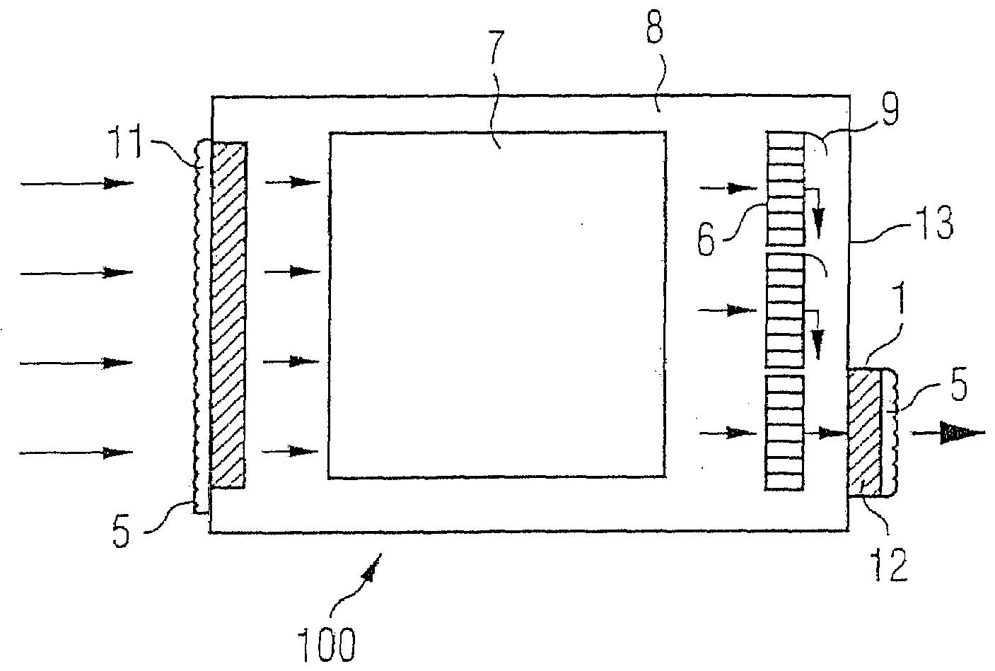
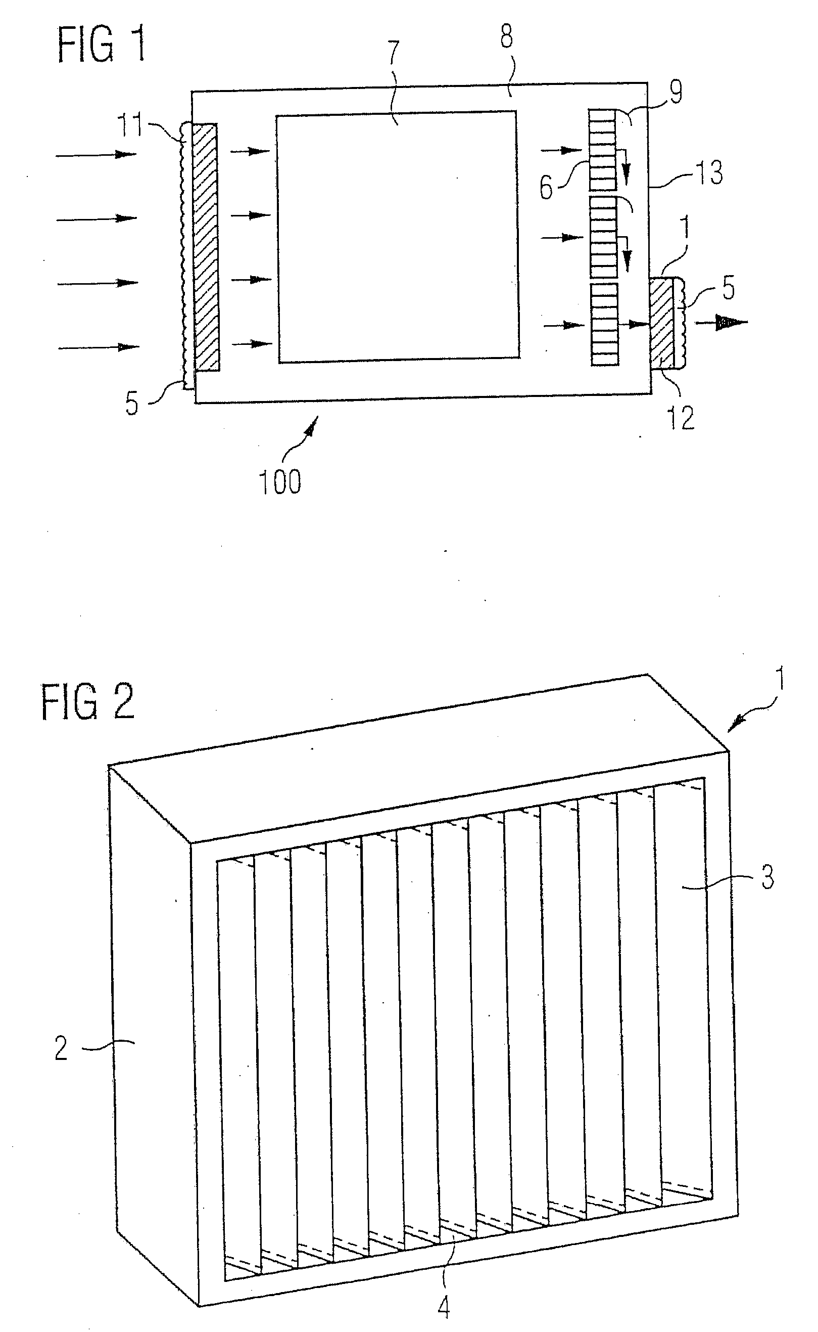
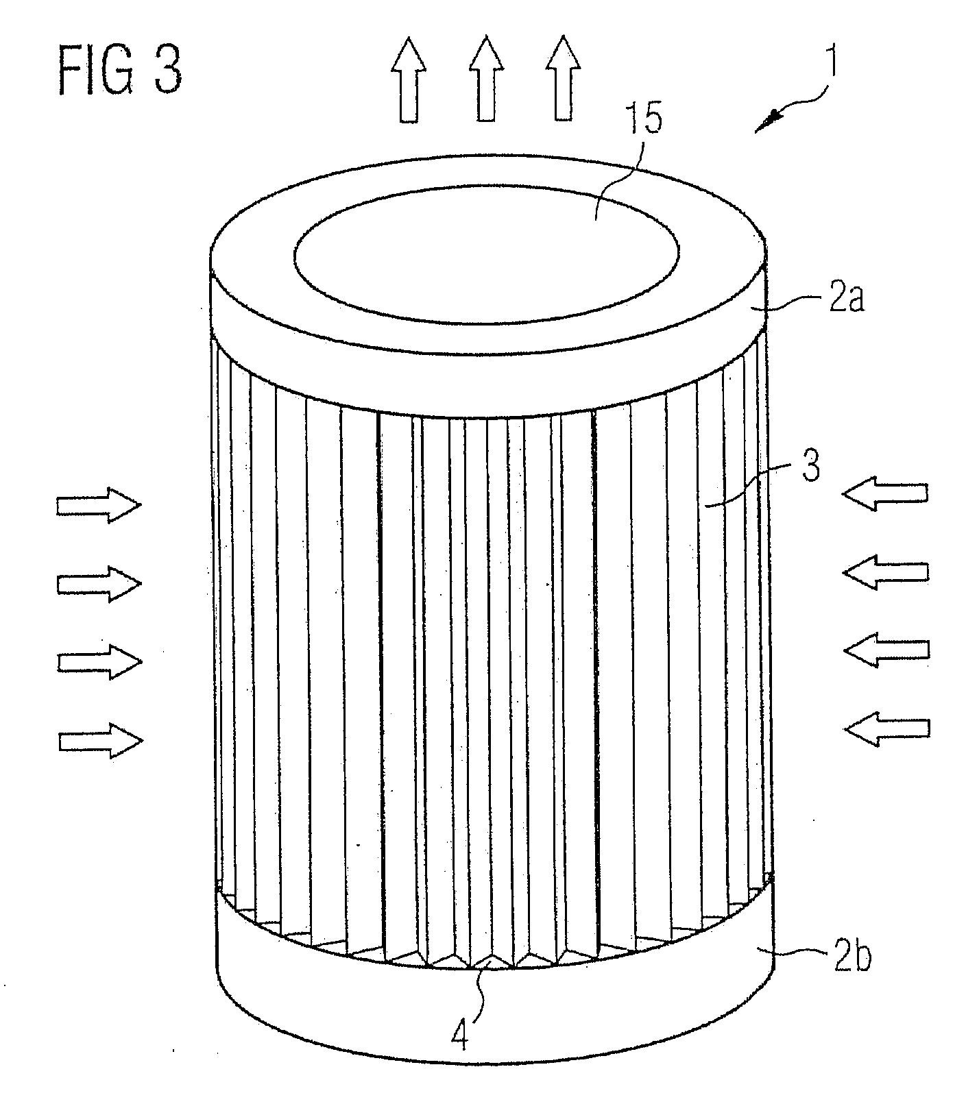
A fan cooling unit (10) for cooling electronic components, such as for an air-cooled telecommunications base station, comprises a protective covering for at least the air inlet opening (11) of a casing (8) in which the electronic components are housed. The protective covering (1) has a frame (2) into which a composite filter media (3) is mounted so as to create an air-tight fit. The composite filter media (3) comprises a membrane filtration layer (20) with a porous polymeric membrane, such as expanded polytetrafluoroethylene (ePTFE), and at least one depth filtration layer (18) disposed on an upstream side of the membrane filtration layer (20). The depth filtration media layer comprises fibers having an electrostatic charge. The ePTFE membrane is preferably made from a blend of a PTFE homopolymer and a modified PTFE polymer.

Description

BACKGROUND[0001]The present invention relates to a fan cooling unit for cooling electronic components, in particular for use in locations exposed to the weather, such as in air-cooled telecommunications base stations.[0002]A prior art fan cooling unit for an air-cooled telecommunications base station is described in WO 00 / 04980. It comprises a casing to take the electronic telecommunications components, at least one air inlet opening and at least one air outlet opening in the casing, at least one fan to produce a flow of air from the air inlet opening through the casing to the air outlet opening, and at least one protective covering to entirely cover at least the air inlet opening so as to remove particles from the air stream entering the casing. The protective covering comprises a composite filter media and a frame in which the composite filter media is mounted so as to create an air tight fit between the filter media and the frame. The filter media comprises a membrane filtration ...

Claims


Application Information

Patent Timeline
Patent Type & Authority Applications(United States)
IPC IPC(8): B03C3/30B01D39/08
CPCB01D39/163H05K7/20181B01D39/1692B01D39/00B01D39/08B01D39/18
Inventor SCHWARZ, ROBERTRUDOLF, CHRISTIANEPOON, WAI SINGMULLER, JASON W.
Owner SCHWARZ ROBERT
Why Eureka
Try Eureka