Light source control device, illuminaton device, and liquid crystal display device

a technology of light source control and illuminaton, which is applied in the direction of optical radiation measurement, instruments, spectrometry/spectrophotometry/monochromators, etc., can solve the problems of obstructing the appropriate detection, deteriorating the display performance of the device, and changing brightness and chromaticity

Inactive Publication Date: 2009-06-04
SHARP KK
View PDF7 Cites 113 Cited by
  • Summary
  • Abstract
  • Description
  • Claims
  • Application Information

AI Technical Summary

Benefits of technology

[0049]With the above configuration, emission brightness of a light source can be appropriately detected and the emission brightness of the light source can be corrected. Accordingly, a light emitting device capable of maintaining a uniform color under various environments can be provided.

Problems solved by technology

Here, an LED has a problem that the display performance thereof is deteriorated by changes in brightness and chromaticity, caused by the environment in which the LED is used, particularly, by the temperature.
Thus, when LEDs are used as light sources, chromaticity of the light sources changes in accordance with the elapse of time and also with a rise in the temperature, thereby causing a deviation in the chromaticity.
Patent Document 5 points out a problem that when light from a specific light source enters a sensor from a light guiding plate, brightness of incident light having a certain angle is high, and an influence of this certain angle obstructs the appropriate detection of light by the planar light source.

Method used


Image

  • Light source control device, illuminaton device, and liquid crystal display device
  • Light source control device, illuminaton device, and liquid crystal display device
  • Light source control device, illuminaton device, and liquid crystal display device

Examples


first embodiment

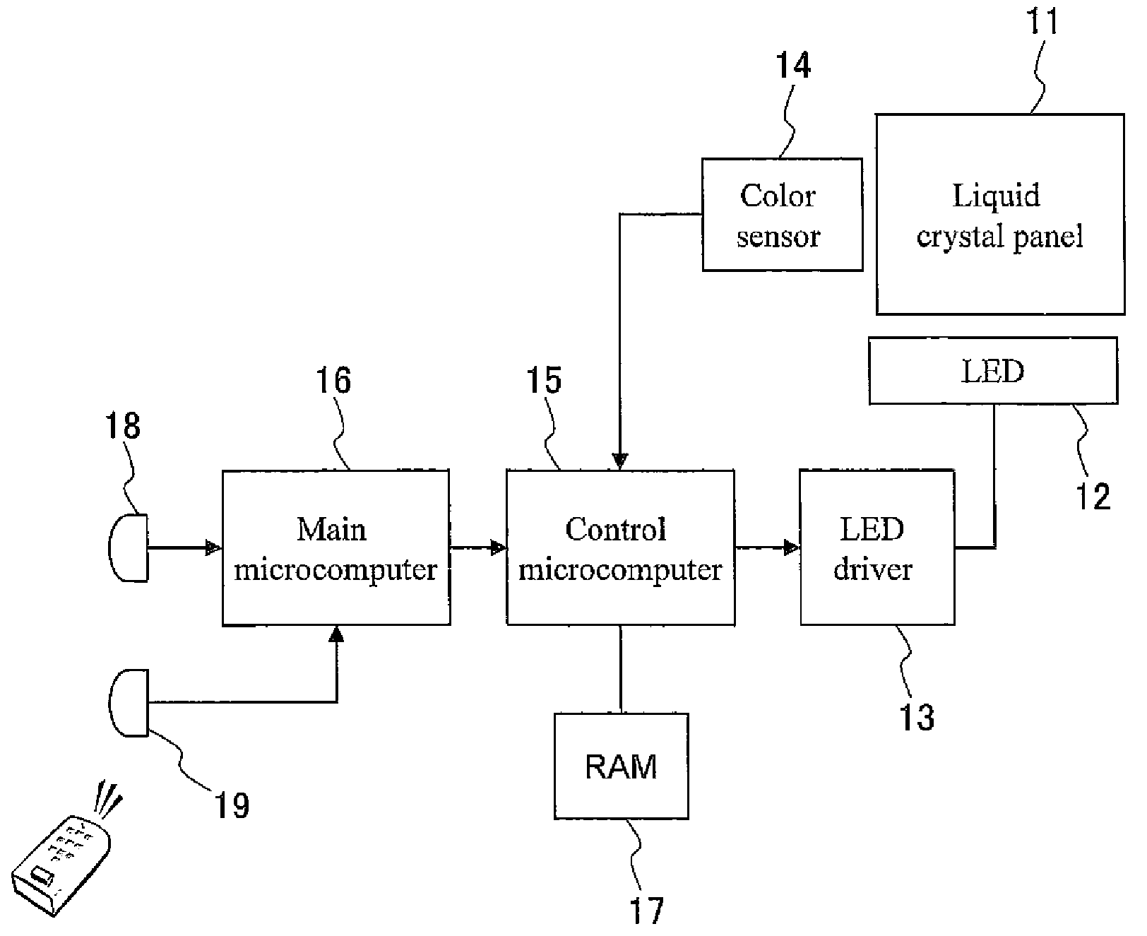
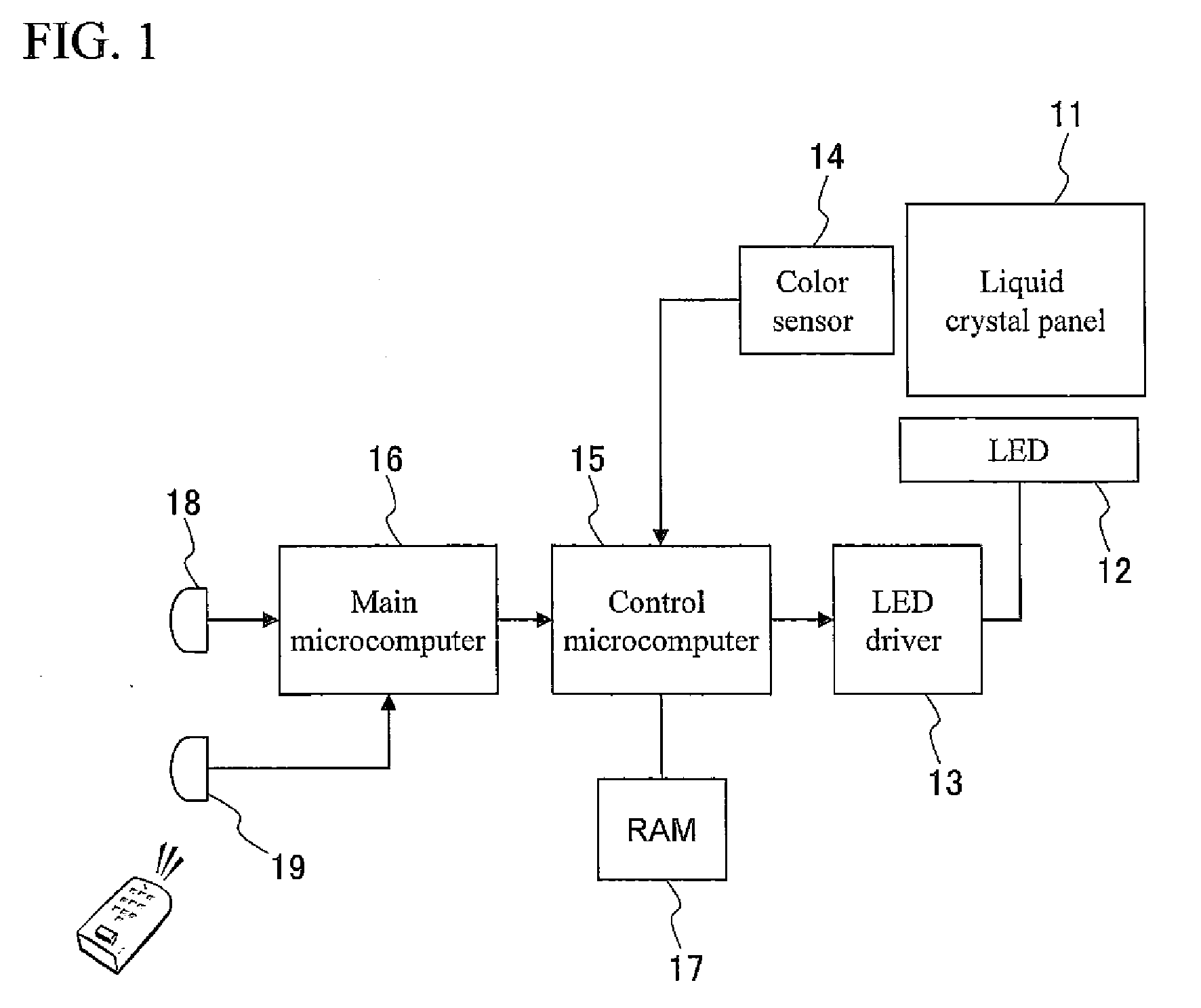
[0136]A description will be given for a liquid crystal display device as an example of a light source control device according to the present invention. FIG. 1 is a block diagram of the liquid crystal display device according to the embodiment.

[0137]The liquid crystal display device includes: a liquid crystal panel 11 for displaying an image; LEDs 12 as light sources for backlighting the liquid crystal panel 11; an LED driver 13 for driving the LEDs 12; a color sensor 14 for detecting emission intensity of each luminescent color of a plurality of LEDs 12; a control microcomputer 15 for giving a drive signal for the LEDs 12 to the LED driver 13; a main microcomputer 16 for giving control information for the LEDs 12 to the control microcomputer 15, on the basis of a detection result from a remote controller signal receiver 19 that detects instruction information, from an illuminance sensor 18 that detects ambient light and from a remote controller of a user; and a RAM 17 for housing a...

second embodiment

[0159]FIG. 8 shows a block diagram of a liquid crystal display device of the present embodiment. The present embodiment is different from the first embodiment in that the LEDs 12 emit light of a single color instead of emitting light of a plurality of colors, and that the liquid crystal display device includes, as light sources, not only the LEDs but also fluorescent lamps (CCFLs) 81 and a CCFL inverter 82 that drives the CCFLs 81.

[0160]FIGS. 9A and 9B show a backlight device serving as an illumination device obtained by removing a liquid crystal panel and an optical member from the liquid crystal display device. FIG. 9B is a view showing the backlight device seen from the front (front view), and FIG. 9A is a view showing the backlight device seen from the side along a dashed line A in FIG. 9B (sectional view).

[0161]The backlight device is a so-called direct type backlight device in which a plurality of fluorescent lamps 4 are arranged so that longitudinal directions thereof are set...

third embodiment

[0177]A description will be given for a backlight device serving as an illumination device according to a third embodiment with reference to FIGS. 14A, 14B and 15.

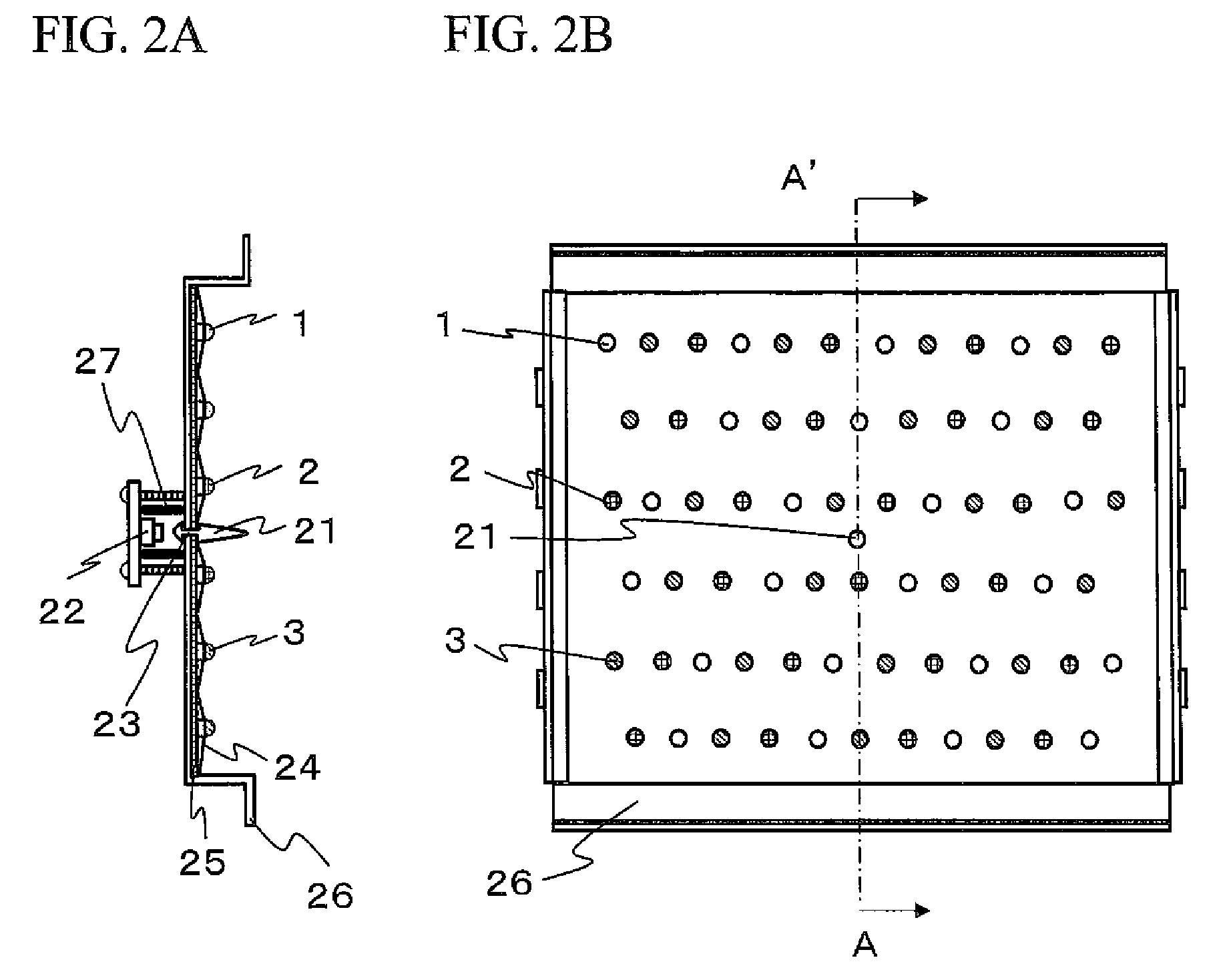
[0178]FIGS. 14A and 14B show a backlight device serving as an illumination device obtained by removing a liquid crystal panel and an optical member from the liquid crystal display device. FIG. 14B is a view showing the backlight device seen from the front (front view), and FIG. 14A is a view showing the backlight device seen from the side along a dashed line A in FIG. 14B (sectional view).

[0179]As similar to the first embodiment, the present embodiment employs a configuration in which a plurality of color sensors 22 are provided on the opposite side to the light source side across the reflector 24. Along with these sensors, provided are a plurality of light guiding bodies 21, and a plurality of sensor housing rooms 22a each formed by a sensor arrangement substrate 33 and a light shielding wall 34.

[0180]With such a configur...


PUM


Abstract

A light emission device capable of holding a uniform color in various environments. A light source control device has a light detection device for detecting emission brightness of light sources that emit different colors and controlling emission brightness of at least one light source of the light sources based on the detection result of the light detection device. A through-hole is formed in a reflection member for reflecting light emitted from the light source, and the reflection is in a predetermined direction. The light detection device is provided across the reflection member from the light source, and the light propagation member is provided at the through-hole.

Description

TECHNICAL FIELD[0001]The present invention relates to a technique for controlling emission brightness of a light source to correct a deviation in chromaticity.BACKGROUND ART[0002]In a passive type image display device which displays an image on a panel by use of light emitted from a light source to the panel, currently, a white cold cathode fluorescent lamp is mainly used as the light source.[0003]On the other hand, a light emitting diode (hereinafter abbreviated as “LED”) has the following advantages. Specifically, the LED can emit light of high brightness. The color reproduction range of the LED can be broadened, and further the LED has a long operation life. Moreover, with an improvement in conversion efficiency, which has conventionally been low, as well as a reduction in costs, the LED has been used as a light source of the above-mentioned passive type image display device.[0004]FIGS. 29A and 29B show a backlight device (direct type) of a liquid crystal display device, which is...

Claims


Application Information

Patent Timeline
Patent Type & Authority Applications(United States)
IPC IPC(8): H05B39/04
CPCG01J1/0271H05B37/0272G01J1/0407G01J1/0422G01J1/32G01J1/4228G01J3/14G01J2003/1213G02B6/0063G02B6/0068G02F1/13318G02F1/133603G02F1/133609H05B33/0821H05B33/0863H05B33/0869H05B35/00G01J1/04H05B45/20H05B45/22H05B45/40H05B47/19
Inventor KOHASHIKAWA, SEIJIFUJINE, TOSHIYUKI
Owner SHARP KK
Why Eureka
Try Eureka