Touch screen system with light reflection

a technology of light reflection and touch screen, applied in the field of touch screens, can solve the problems of easy deformation or damage of the touch screen panel, design drawback of incurring a higher cost, etc., and achieve the effects of enhancing the life and popularity of the touch screen, reducing manufacturing costs, and fast signal transmission

Inactive Publication Date: 2009-06-04
LUNGHWA UNIVERSITY OF SCIENCE AND TECHNOLOGY
View PDF4 Cites 9 Cited by
  • Summary
  • Abstract
  • Description
  • Claims
  • Application Information

AI Technical Summary

Benefits of technology

[0006]Therefore, it is a primary objective of the present invention to provide a touch screen system with light reflection, and the touch screen system comprises an LED infrared transceivers installed at appropriate positions on both left and right sides of the screen respectively, and a transmitter end of the transceiver transmits LED infrared waves and spreads spherical waves all over the surface of the screen, such that if the surface of the screen receives an intrusion from the touch control element, the spherical waves will be interfered, interrupted and reflected, and the wave frequency of the reflection will be detected by the receiver end of the transceiver. After the receiver end has received a reflection signal, the position coordinates of the touch control element can be analyzed through the operation of a core logical unit. In addition to the advantages of low manufacturing cost and fast signal transmission, the present invention also overcomes the aforementioned shortcoming of the traditional capacitance type touch screen being deformed or damaged easily by repeated exertions of stress to enhance the life and popularity of the touch screen.

Problems solved by technology

However, such arrangement of using the change of capacitance to determine the position of the user's finger or the conductor exert stresses repeatedly on the touch screen panel, and this design has the drawback of deforming or damaging the touch screen panel easily.
Obviously, this design has the drawback of incurring a higher cost.

Method used


Image

  • Touch screen system with light reflection
  • Touch screen system with light reflection
  • Touch screen system with light reflection

Examples


Embodiment Construction

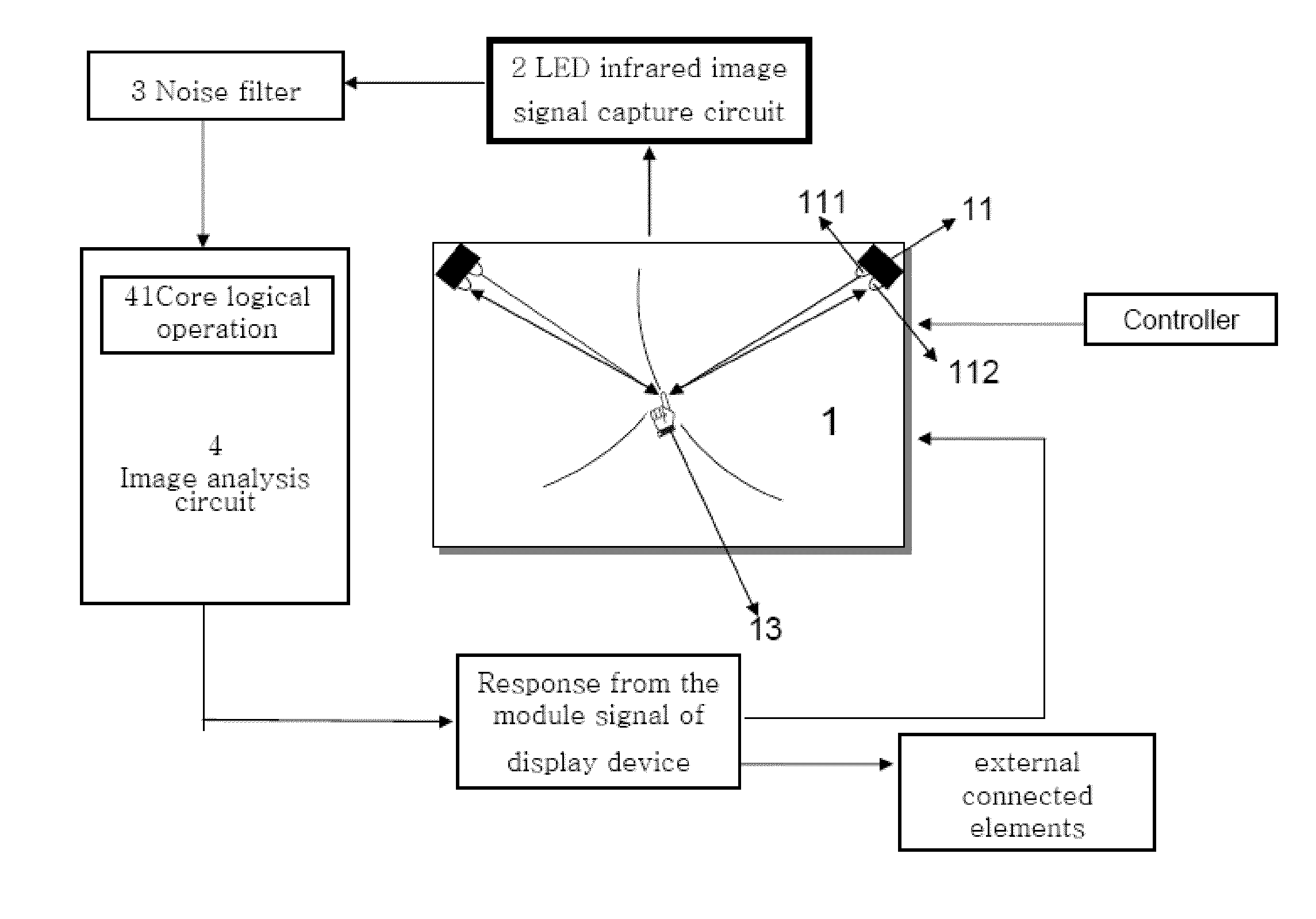
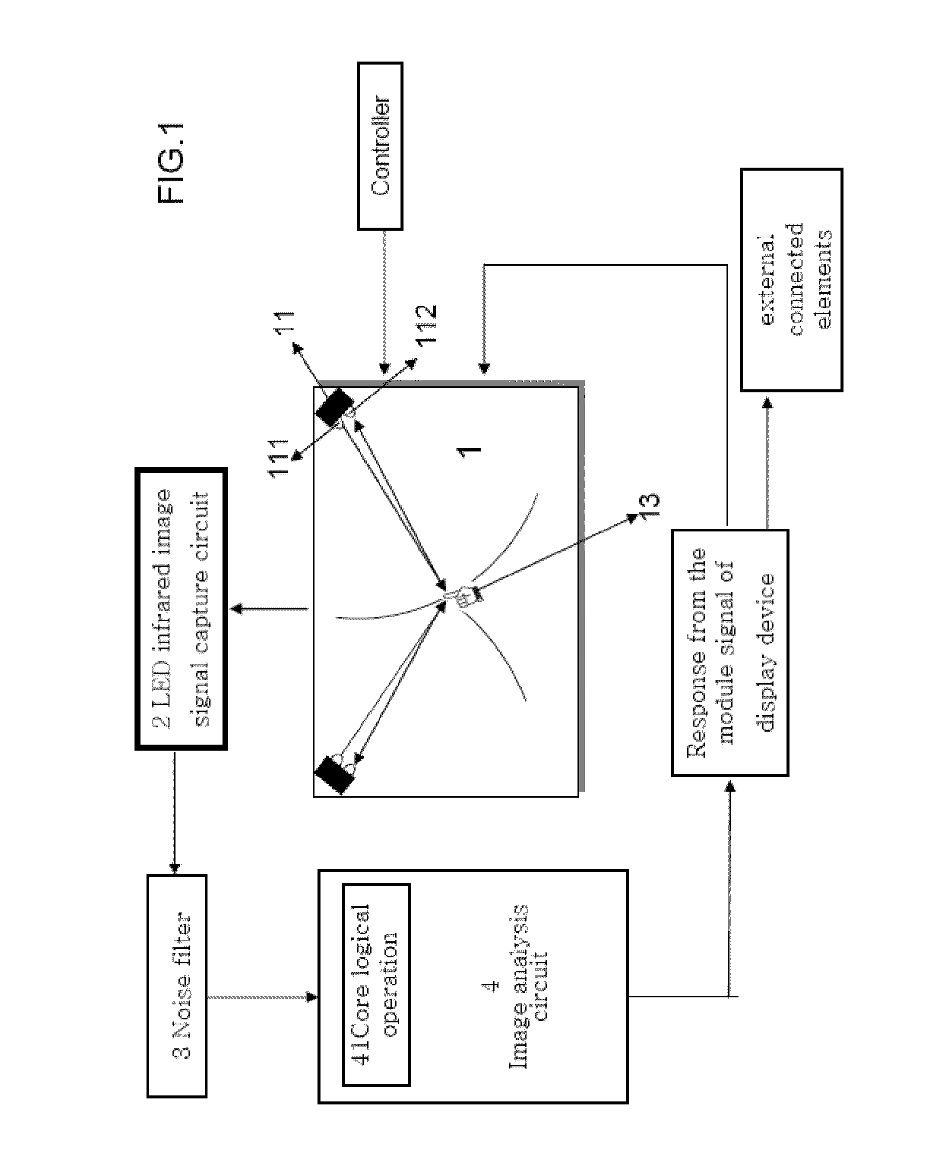
[0009]With reference to FIG. 1, a touch screen system in accordance with a preferred embodiment of the present invention comprises a screen 1 and an LED infrared transceiver 11 disposed separately at appropriate positions on both sides of the screen 1 and having a transmitter end 111 and a receiver 112 for transmitting and receiving LED infrared waves respectively. The LED infrared waves transmitted from the transmitters 111 on both sides form spherical waves all over the entire screen 1 to constitute an image signal detection net, such that if a touch control element 13 intrudes the image signal detection net, the LED infrared waves will be interrupted and reflected, and the receiver end 112 will be able to receive the reflected waves to capture target images and transmit the target images to an LED infrared image signal capture circuit 2 electrically coupled to the receiver end 112. After going through a noise filter 3, the target images are transmitted to an image analysis circui...


PUM


Abstract

The present invention discloses a touch screen system comprising LED infrared transceivers installed at appropriate positions on left and right sides of the screen respectively, and a transmitter end of the transceiver transmits LED infrared waves and spreads spherical waves all over the surface of the screen. If the surface of the screen receives an intrusion from a touch control element, the spherical waves will be interfered, interrupted and reflected, and the wave frequency of the reflection will be detected by the receiver end of the transceiver. After the receiver end has received a reflection signal, the position coordinates of the touch control element can be analyzed through the operation of a core logical unit. A display module is provided for showing the movement path of the touch control element in images or lines, so as to provide a touch screen with low manufacturing cost and long life expectancy.

Description

[0001]This application is a Continuation-In-Part of my patent application, Ser. No. 12 / 258,466, filed on Oct. 27, 2008.FIELD OF THE INVENTION[0002]The present invention generally relates to touch screens, and more particularly to a touch screen system wherein the light emitting diode (LED) infrared waves is reflection interrupted.BACKGROUND OF THE INVENTION[0003]In a traditional touch screen, a sensor generally comes with a digital capacitance structure having two sensing layers installed at the top and bottom of a touch screen panel respectively and coupled to a control circuit, such that a capacitance effect is produced instantaneously when a user touches the touch screen panel by a finger or a conductor. However, such arrangement of using the change of capacitance to determine the position of the user's finger or the conductor exert stresses repeatedly on the touch screen panel, and this design has the drawback of deforming or damaging the touch screen panel easily.[0004]Later, m...

Claims


Application Information

Patent Timeline
Patent Type & Authority Applications(United States)
IPC IPC(8): G06F3/042
CPCH01L23/13H01L23/49816H01L2924/12041H01L2224/32245H01L2224/32225H01L2224/16225H01L2224/73215H01L2924/014H01L2924/01033H01L24/48H01L2924/30105H01L2924/19107H01L2924/15311H01L2924/01082H01L23/49827H01L24/49H01L2224/16H01L2224/48091H01L2224/4824H01L2224/4911H01L2224/49174H01L2924/01002H01L2924/01005H01L2924/00014H01L2924/00H01L2224/451H01L2924/351H01L24/45H01L2924/181H01L2224/05573H01L2224/05568H01L2224/056H01L2224/73204H01L24/05H01L2924/00012
Inventor WEN-PEN, WENGHUI, KO WEN
Owner LUNGHWA UNIVERSITY OF SCIENCE AND TECHNOLOGY
Why Eureka
Try Eureka