

Scr catalyst for removal of nitrogen oxides
- Summary
- Abstract
- Description
- Claims
- Application Information
AI Technical Summary
Benefits of technology
Problems solved by technology
Method used
Image

Examples
Embodiment Construction
[0026]The present invention will be further illustrated by the following examples in order to provide a better understanding of the invention. However, the present invention is not limited to the examples, and particularly, the substances that compose each layer can be other substances that are within the technical effect of the present invention.
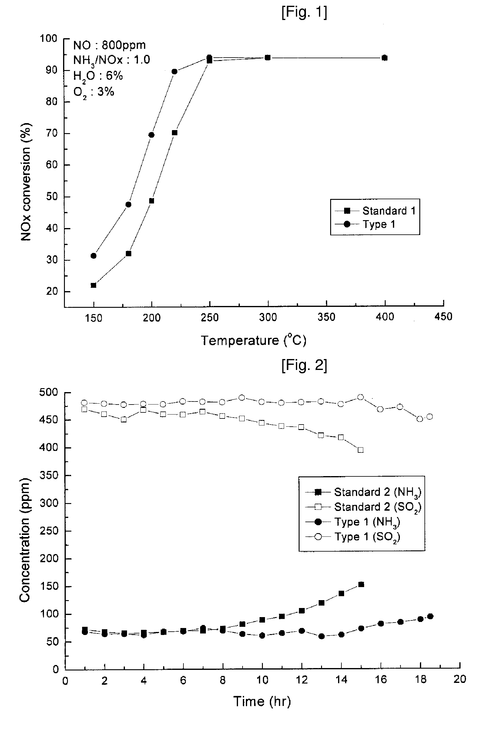
[0027]FIG. 1 shows NO conversion without the presence of antimony according to Reference 1 (standard 1) and one with antimony at different temperatures according to Example 1 (type 1) of the present invention.
[0028]Reference 1 uses titanium oxide (TiO2) carrier, without antimony added and impregnated with 2 wt. % of vanadium as an active material. Example 1 uses titanium oxide (TiO2) carrier which is impregnated with 2 wt. % of vanadium as an active material and 2 wt. % of antimony oxide as a minor catalyst. The amounts of nitrogen oxides and ammonia used are each 800 ppm, the amount of water is 6%, and the amount of oxygen is 3%.
[0029]FIG....
PUM
| Property | Measurement | Unit |
|---|---|---|
| Electrical resistance | aaaaa | aaaaa |
| Catalytic activity | aaaaa | aaaaa |
Abstract
Description
Claims
Application Information