Self-adjusting seal for a heat exchanger

a heat exchanger and self-adjusting technology, applied in indirect heat exchangers, lighting and heating apparatus, other domestic objects, etc., can solve the problems of reducing the thermal efficiency of heat exchangers, and affecting the operation of seals

Inactive Publication Date: 2009-06-11
PARAGON AIRHEATER TECH
View PDF24 Cites 28 Cited by
  • Summary
  • Abstract
  • Description
  • Claims
  • Application Information

AI Technical Summary

Benefits of technology

[0010]In accordance with one embodiment, a self-adjusting seal assembly for a regenerative heat exchanger having a housing and a heat exchanging body disposed within the housing is provided, where the heat exchanging body configured to rotate in a first direction relative to the housing, the seal assembly extending between the heat exchanging body and the housing and defining an interface therebetween. The seal assembly comprises a base plate removably coupleable to a wall of the heat exchanging body configured to rotate about an axis of the heat exchanging body. A flexible portion is disposed adjacent a portion of the base plate and is coupled to the base plate at desired intervals along their entire lengths, the flexible portion configured to extend between an edge of the wall and an inner surface of the housing. A contact plate is disposed adjacent a portion of the flexible portion and coupled to the flexible portion at desired intervals along their entire lengths, the contact plate configured to contact the housing as the heat exchanging body rotates to inhibit leakage of air between the heat exchanging body and the housing. At least one of the flexible portion and contact plate deflect in a second direction opposite the first direction such that a stress generated by said deflection is substantially concentrated in the flexible portion, said deflection adjusting automatically such that contact is maintained between the contact plate and the inner surface of the housing during operation of the regenerative heat exchanger.
[0011]In accordance with another embodiment, a regenerative heat exchanger is provided. The heat exchanger comprises a housing defining a first conduit and a second conduit, each of the first and second conduits configured to receive airflow therethrough and a heat exchanging body disposed within the housing, the heat exchanging body configured to rotate in a first direction relative to the housing so that portions of the heat exchanging body are alternatingly exposed to the first conduit and second conduit. The heat exchanger also comprises at least one seal extending between the heat exchanging body and the housing, the seal configured to contact the housing as the heat exchanging body rotates to inhibit leakage of air between the first and second conduits, the seal further configured to flex in a second direction opposite the first direction. The seal comprises a base plate removably coupleable to a wall of the heat exchanging body configured to rotate about an axis of the heat exchanging body and a flexible metal sheet disposed adjacent a portion of the base plate and coupled to the base plate at desired intervals along their entire lengths, the flexible metal sheet configured to extend between an edge of the wall and an inner surface of the housing. The seal also comprises a contact plate disposed adjacent a portion of the flexible metal sheet and coupled to the flexible metal sheet at desired intervals along their entire lengths, the contact plate configured to contact the housing as the heat exchanging body rotates to inhibit leakage of air between the heat exchanging body and the housing. At least one of the flexible metal sheet and contact plate deflect in a second direction opposite the first direction such that a stress generated by said deflection is substantially concentrated in the flexible metal sheet, said deflection adjusting automatically such that contact is maintained between the contact plate and the inner surface of the housing during operation of the regenerative heat exchanger

Problems solved by technology

As is also known in the art, leakage between the hot gas conduit and the cold air conduit reduces the thermal efficiency of heat exchangers.
Unfortunately, conventional seals have many disadvantages.
For example, seals are typically exposed to harsh operating conditions, such as erosive fly ash and soot.
As the heat exchanging body moves with respect to the housing or vice versa, the seals are also exposed to mechanical abuse because the seals are positioned to maintain sliding contact with the sealing surfaces.
Consequently, the seals wear down quickly.
Further, the high operating temperatures of the heat exchanging apparatus expose the seals to thermal stresses which often cause the seals to warp.
The high operating temperature also causes thermal distortions in the shape of the structural members of the heat exchanging apparatus, such as the housing and center shaft.
The distortions in the shape of the seals and the structural members affect the clearance between the seals and the sealing surfaces, often resulting in leakage paths between the hot gas conduit and the cold air conduit.
Such leakage paths typically reduce the thermal efficiency of the heat exchanging apparatus and also reduce the overall efficiency of the system.
Conventional seal designs do not adequately address these problems.
However, such seals are not very flexible and often lose contact with the sealing surface when the structural members of the heat exchanging apparatus thermally distort.
However, such seals hold up poorly to corrosion and mechanical abuse.
However, such seals may fracture or break when flexibly responding to torque stress loads that are produced by rotation of the heat exchanging body with respect to the housing of the heat exchanger.
As a result, stress fractures may allow gas leakage between conduits.

Method used


Image

  • Self-adjusting seal for a heat exchanger
  • Self-adjusting seal for a heat exchanger
  • Self-adjusting seal for a heat exchanger

Examples


Embodiment Construction

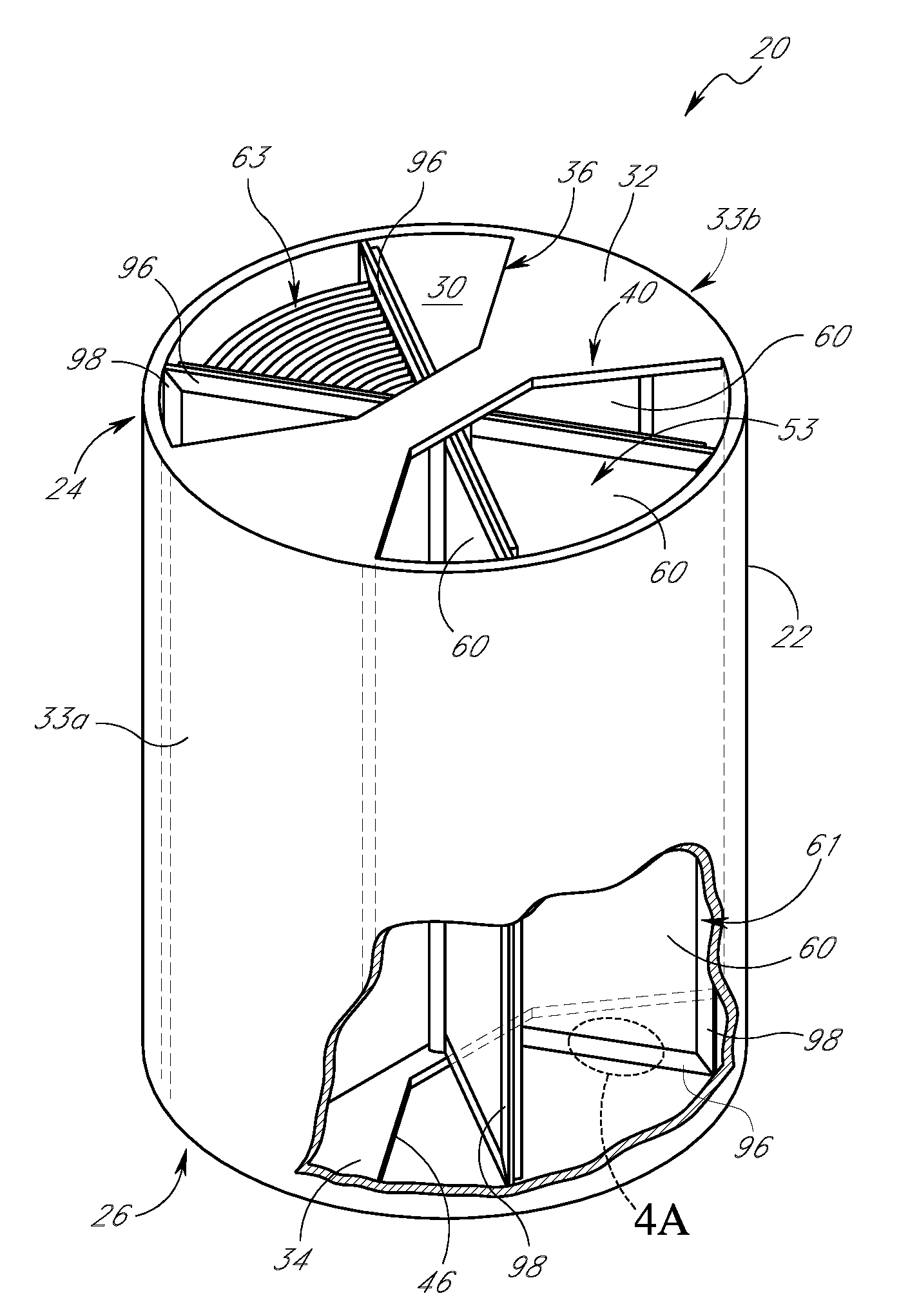
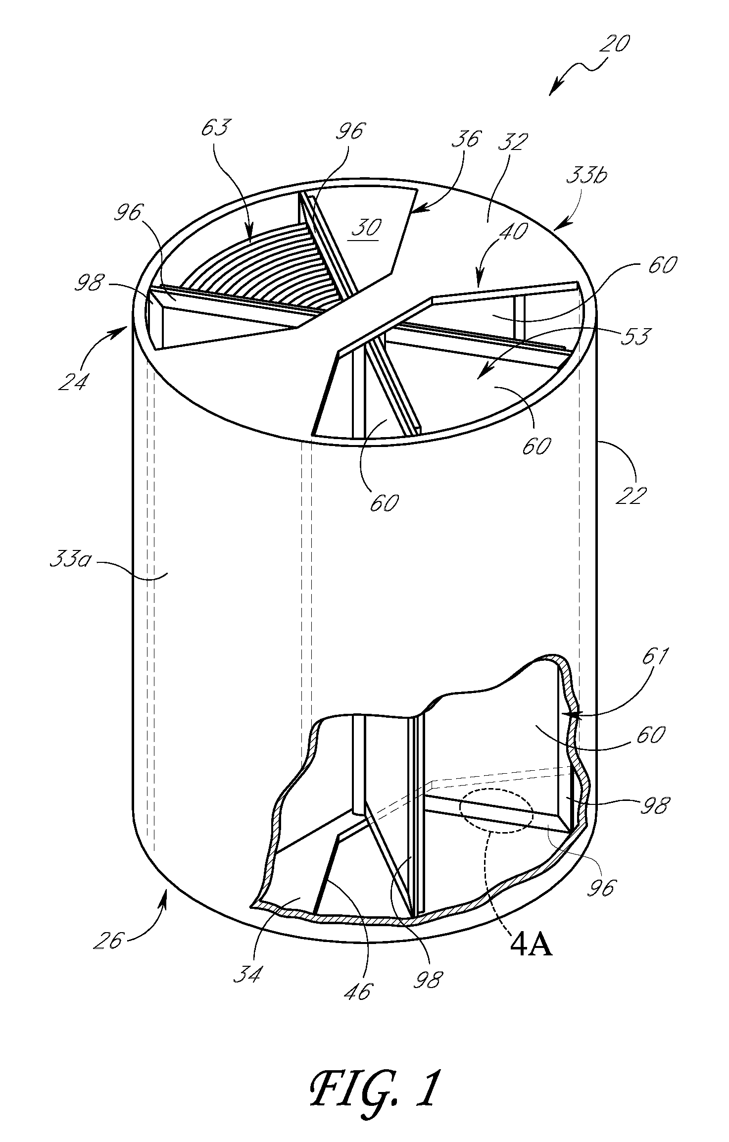
[0020]Reference will now be made to the drawings wherein like numerals refer to like parts throughout. FIG. 1 is a perspective view of one embodiment of a regenerative heat exchanging apparatus (or heat exchanger) 20 in which seal assemblies 96, 98 (shown in FIGS. 4A-4C) are used. FIG. 2 illustrates a top view of the heat exchanging apparatus 20 of FIG. 1. The heat exchanging apparatus 20 includes a housing 22 that can have a substantially cylindrical shape. The housing 22 has a top end 24 and a bottom end 26. As used herein, the words “top” and “bottom” are with respect to the drawings and are not intended to limit the scope of the invention. In one embodiment, the heat exchanging apparatus 20 can be a Ljungstrom™-type Air Preheater. However, the heat exchanging apparatus 20 can be any suitable regenerative heat exchanger (e.g., Rothemuhle®-type Regenerative Air Preheater). Further details on regenerative heat exchangers and associated members can be found in U.S. Pat. No. 5,950,70...


PUM


Abstract

Disclosed is an improved sealing element for a regenerative heat exchanging apparatus, such as a Ljungstrom™-type or other suitable regenerative heat exchangers. The sealing element can be mounted to a wall of the rotor of the heat exchanger to provide a secure seal between the wall and a housing of the heat exchanger, thereby inhibiting the leakage of gas between the hot gas conduit and cool air conduit of the regenerative heat exchanger. In one embodiment, the sealing element includes a base plate that is used to mount the sealing element to the wall. The sealing element also includes a contact shoe that maintains a sealing contact between the wall and housing. A flexible portion is coupled between the base plate and contact shoe to provide the sealing element with flexibility and resiliency so that the sealing element maintains contact with the sealing surface even when the heat exchanging apparatus experiences warping and / or distortion from thermal stress. The stress from the deflection of the seal during operation of the heat exchanger is substantially concentrated in the flexible portion of the seal.

Description

BACKGROUND OF THE INVENTION[0001]1. Field of the Invention[0002]The present invention relates to heat exchange technology and, in particular, relates to a self-adjusting radial seal for a heat exchanger that may be used to reduce leakage between a hot gas conduit and a cold air conduit of a regenerative heat exchanging system.[0003]2. Description of the Related Art[0004]Conventional regenerative heat exchangers are used to provide preheated air to heavy machinery, such as a fuel burning power plant, and may be used with various types of machinery that exhaust hot gas and operate more efficiently when supplied with preheated air, such as, for example, chemical processors, refineries, pulp and paper mills, and ships. Typically, two fluid stream passages extend through the heat exchanger. The first passage may include a hot gas conduit that communicates with a hot exhaust outlet of the power plant. Hot exhaust gases flow from the power plant exhaust into the hot gas conduit of the heat...

Claims


Application Information

Patent Timeline
Patent Type & Authority Applications(United States)
IPC IPC(8): F23L15/02B23P15/26
CPCF23L15/02Y10T29/49357F28D19/047Y02E20/34
Inventor KLISURA, FRANK
Owner PARAGON AIRHEATER TECH
Why Eureka
Try Eureka