Non-linear fin heat sink

a heat sink and non-linear technology, applied in lighting and heating apparatus, tubular elements, semiconductor devices, etc., can solve the problems of low flow resistance and low heat transfer, high heat loss, and high heat loss, and achieve high power density and dissipation/removing heat

Inactive Publication Date: 2009-06-11
THERMAL TECH
View PDF21 Cites 191 Cited by
  • Summary
  • Abstract
  • Description
  • Claims
  • Application Information

AI Technical Summary

Benefits of technology

[0039]In view of the foregoing, it is an object of the present invention to provide heat sink method and apparatus which are c

Problems solved by technology

Also, fin patterns that produce greater cross sectional flow area between fins will have higher turbulence.
Such an arrangement can yield a high heat transfer coefficient at higher flow resistance in the original orientation but will offer low

Method used


Image

  • Non-linear fin heat sink
  • Non-linear fin heat sink
  • Non-linear fin heat sink

Examples


Embodiment Construction

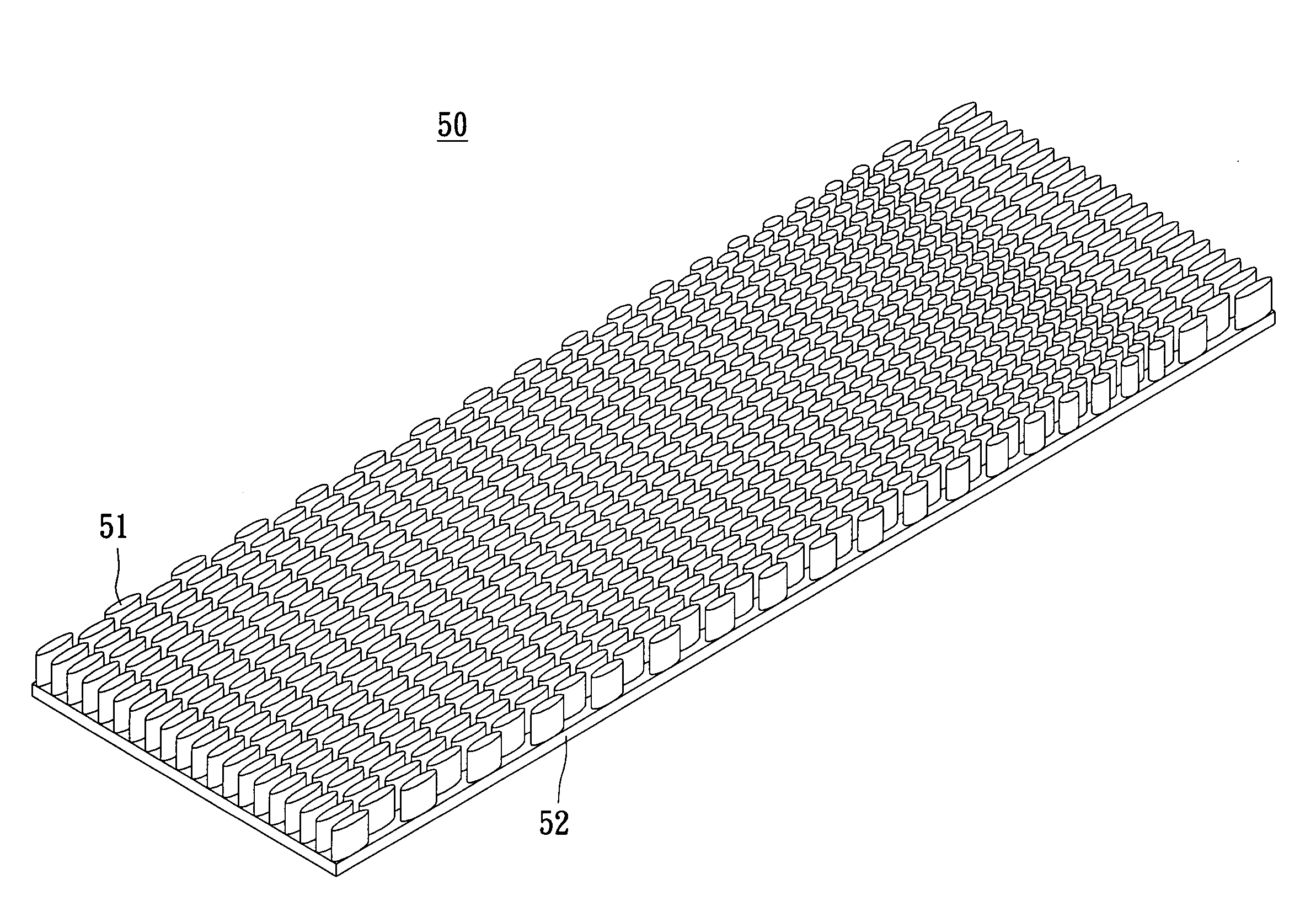
[0106]Referring to FIG. 5, a non-linear fin heat sink 50 is shown. The fins 51 are cross-sectionally shaped as ellipses and attached to a heat sink base 52.

[0107]Referring now to FIG. 6, each elliptical fin 51 has a cross-sectional fin longitudinal dimension 53 and a cross-sectional fin transverse dimension 54. Longitudinal fin spacing (distance between two consecutive fins in the longitudinal direction, i.e., within a given row 55) is represented as 56, and the transverse fin spacing (distance between two consecutive rows 55 or fins 51 in the transverse direction) is represented as 57. Longitudinal rows 55 are in staggered relationship with each other so that fins 51 in alternating longitudinal rows 55 are transversely (columnarly) 58 aligned.

[0108]Referring now to FIG. 7 of the present invention 50, upper lid 59 and base 52 act as boundary layers for flow. Upper lid 59 and base 52 are both planar. Elliptical fins 51 extend an overall fin height 60 from upper surface of the base 52...


PUM


Abstract

A non-linear fin heat sink is provided for dissipating/removing heat uniformly from a device, where the heat generation is non-uniform over that device, while also providing a small and relatively lightweight heat sink. The heat sink has extended surface protrusions that are optimally shaped in recognition of convective heat transfer, conductive heat transfer, and flow resistance allowing the heat sink to offset the temperature rise of a coolant media and provide enhanced cooling for the coolant temperature, deliver optimized cooling efficiency per the local physical properties of the coolant media, be used with a fluid for effectuating heat transfer; either liquid coolant, gas coolant or a combination thereof. Furthermore the heat sink features turbulence enhancement of the coolant stream by a pin array through which coolant stream passes, such fin array featuring a non-linear shape, spacing, and height pattern to provide optimal cooling while simultaneously reducing volume and flow resistance.

Description

BACKGROUND OF THE INVENTION[0001]1. Field of the Invention[0002]The present invention relates to methods and apparatuses for heat transfer. More particularly, the invention relates to optimized extended surfaces used for cooling electronic components and other objects whereas such methods and apparatuses involve heat transfer, such as the removal, absorption and / or dissipation of heat.[0003]2. Description of the Related Art[0004]A “heat sink” (alternatively spelled “heatsink”) is a device used for removing, absorbing and / or dissipating heat from a thermal system. Generally speaking, conventional heat sinks are founded on well known physical principles pertaining to heat transference. Heat transference concerns the transfer of heat (thermal energy) via conduction, convection, radiation or some combination thereof. In general, heat transfer involves the movement of heat from one body (solid, liquid, gas or some combination thereof to another body (solid, liquid, gas or some combinatio...

Claims


Application Information

Patent Timeline
IPC IPC(8): F28F7/00
CPCF28F1/40F28F1/42F28F1/422F28F3/022F28F3/14H01L23/467H01L23/473H01L2924/0002F28F2250/02F28F1/006F28F2215/04H01L2924/00
Inventor HOFFMAN, PAULREMSBURG, RALPHREEVES, MATT
Owner THERMAL TECH
Why Eureka
Try Eureka