Enhanced Hydrocarbon Recovery By Steam Injection of Oil Sand FOrmations

a technology of hydrocarbon recovery and oil sand formation, which is applied in the direction of fluid removal, insulation, borehole/well accessories, etc., can solve the problems of large energy consumption of thermal recovery processes using steam, inability to meet the needs of oil sand formation, etc., to achieve the effect of increasing the production of petroleum fluids and enhancing the recovery of petroleum fluids

Inactive Publication Date: 2009-06-11
GEOSIERRA
View PDF84 Cites 15 Cited by
  • Summary
  • Abstract
  • Description
  • Claims
  • Application Information

AI Technical Summary

Benefits of technology

[0023]The present invention is a method and apparatus for enhanced recovery of petroleum fluids from the subsurface by injection of steam in contact with the oil sand formation and the heavy oil and bitumen in situ. Multiple propped hydraulic fractures are constructed from the well bore into the oil sand formation and filled with a highly permeable proppant. Steam is injected into the well bore and the propped fractures at or near the ambient reservoir pressure but substantially below the reservoir fracturing pressure. The injected steam flows upwards and outwards in the propped fractures contacting the oil sands and in situ bitumen on the vertical faces of the propped fractures. The steam condenses onto the cool bitumen and the latent heat of the steam diffuse into the bitumen from the vertical faces of the propped fractures. The bitumen softens and flows by gravity to the well bore, exposing fresh surface of bitumen for the process to progressively soften and mobilize the bitumen in a predominantly circumferential, i.e. orthogonal to the propped fracture, diffusion direction at a nearly uniform rate into the oil sand deposit. To limit upward growth of the process, a light non-condensing gas can be injected to remain in the uppermost portions of the propped fractures. The mobile oil may be deasphalted by co-injection of a hydrocarbon solvent with the steam, leaving the heavy asphaltenes behind in the oil sand pore space with little loss of inherent fluid mobility in the processed oil sands. The processed hydrocarbon product with the dissolved solvent is produced from the formation and steam along with a hydrocarbon solvent is re-injected into the process zone and the cycle repeats.
[0025]The hydrocarbon solvent would preferably be one of ethane, propane, or butane or a mixture thereof, and be mixed with a non-condensing diluent gas being either methane, nitrogen, carbon dioxide, natural gas, or a mixture thereof, to ensure that the selected composition of the injected gas is such that: 1) the solvent mixture has a dew point that substantially corresponds with the operating process temperature and pressure in situ, 2) the solvent mixture is substantially more soluble in the bitumen than the diluent gas, 3) the solvent mixture is liquefied but vaporizable in the process zone, and 4) solvent mixture has a vapor / liquid envelop that encompasses the process operating temperatures and pressures. The solvent and diluent gas are injected with the steam into the well bore and the process zone, with the solvent primarily as a vapor state contacting and diffusing into the bitumen. By selecting the appropriate solvent, diluent gas, and steam mixture, the process can operate close to ambient reservoir pressures, so that water inflow into the process zone can be minimized. The selected range of temperatures and pressures to operate the process will depend on reservoir depth, ambient conditions, quality of the in place heavy oil and bitumen, composition of the solvent, diluent gas and steam mixture, and the presence of nearby water bodies. At such elevated temperatures, the diffusion rate of the solvent diffusing into the bitumen is significantly greater than at reservoir ambient temperatures.
[0028]Therefore, the present invention provides a method and apparatus for enhanced recovery of petroleum fluids from the subsurface by steam and vaporized solvents placed in the oil sand formation contacting the viscous heavy oil and bitumen in situ, and more particularly to a method and apparatus to extract a particular fraction of the in situ hydrocarbon reserve by controlling the access to the in situ bitumen, the steam solvent composition, and operating temperatures and pressures of the in situ process, resulting in increased production of petroleum fluids from the subsurface formation as well as limiting water inflow into the process zone.

Problems solved by technology

Successive steam injection cycles reenter earlier created fractures and thus the process becomes less efficient over time.
CSS is generally practiced in vertical wells, but systems are operational in horizontal wells, but have complications due to localized fracturing and steam entry and the lack of steam flow control along the long length of the horizontal well bore.
Similar to CSS, the SAGD method has complications, albeit less severe than CSS, due to the lack of steam flow control along the long section of the horizontal well and the difficulty of controlling the growth of the steam chamber.
Thermal recovery processes using steam require large amounts of energy to produce the steam, using either natural gas or heavy fractions of produced synthetic crude.
Burning these fuels generates significant quantities of greenhouse gases, such as carbon dioxide.
Also, the steam process uses considerable quantities of water, which even though may be reprocessed, involves recycling costs and energy use.
The startup phase for the VAPEX process can be lengthy and take many months to develop a controlled connection between the two wells and avoid premature short circuiting between the injector and producer.
The VAPEX process with horizontal wells has similar issues to CSS and SAGD in horizontal wells, due to the lack of solvent flow control along the long horizontal well bore, which can lead to non-uniformity of the vapor chamber development and growth along the horizontal well bore.
The thermal and solvent methods of enhanced oil recovery from oil sands, all suffer from a lack of surface area access to the in place bitumen.
Similarly the VAPEX process is limited by the available surface area to the in place bitumen, because the diffusion process at this contact controls the rate of softening of the bitumen.
Likewise during steam chamber growth in the SAGD process the contact surface area with the in place bitumen is virtually a constant, thus limiting the rate of heating of the bitumen.
The hydraulic connectivity of the hydraulic fracture or fractures formed in the formation may be poorly connected to the well bore due to restrictions and damage due to the perforations.
At significant depth, one of the horizontal stresses is generally at a minimum, resulting in a vertical fracture formed by the hydraulic fracturing process.
Such theories and models are highly developed and generally sufficient for the art of initiating and propagating hydraulic fractures in brittle materials such as rock, but are totally inadequate in the understanding and art of initiating and propagating hydraulic fractures in ductile materials such as unconsolidated sands and weakly cemented formations.
Hydraulic fracturing has evolved into a highly complex process with specialized fluids, equipment and monitoring systems.

Method used


Image

  • Enhanced Hydrocarbon Recovery By Steam Injection of Oil Sand FOrmations
  • Enhanced Hydrocarbon Recovery By Steam Injection of Oil Sand FOrmations
  • Enhanced Hydrocarbon Recovery By Steam Injection of Oil Sand FOrmations

Examples


Embodiment Construction

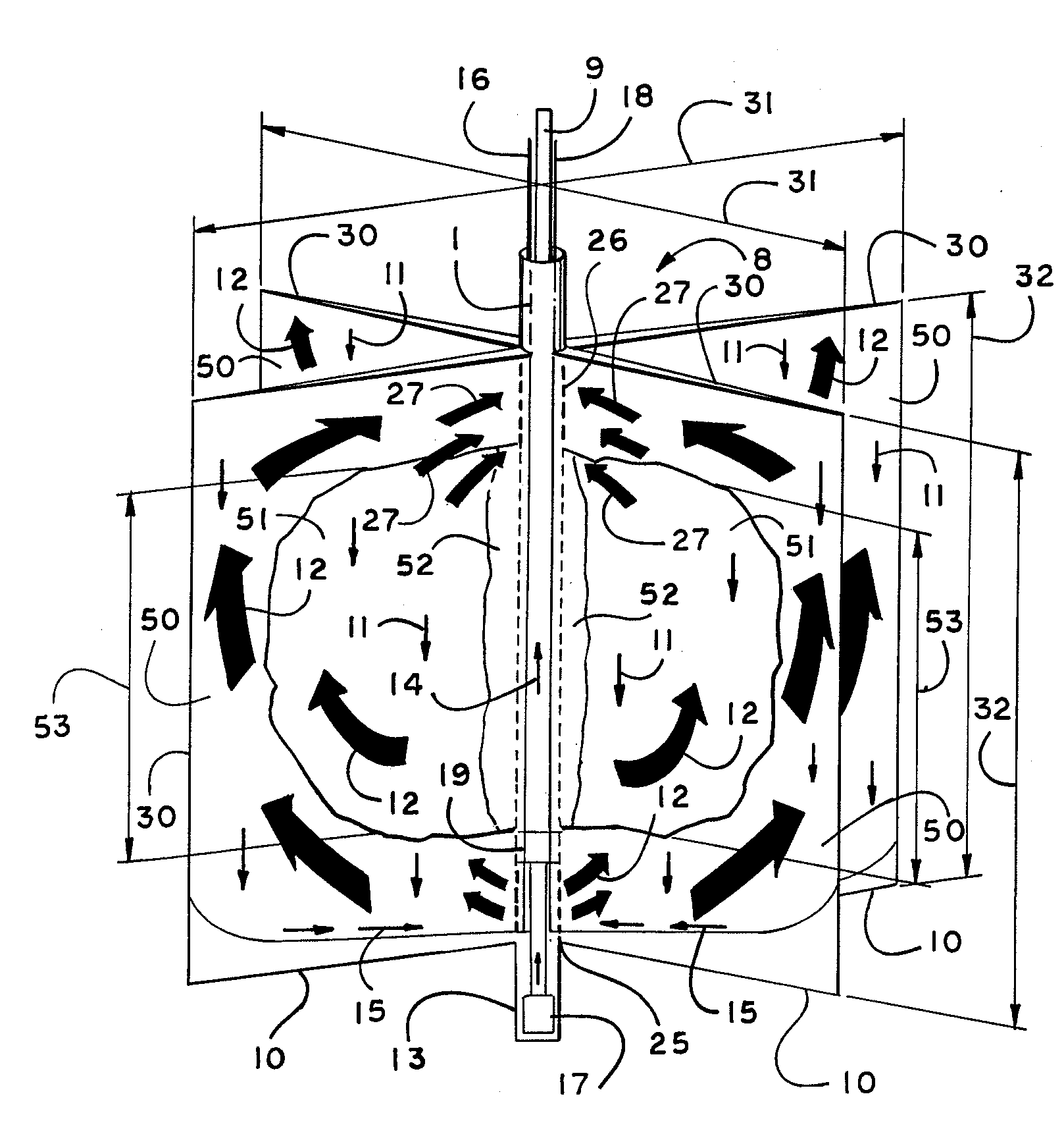
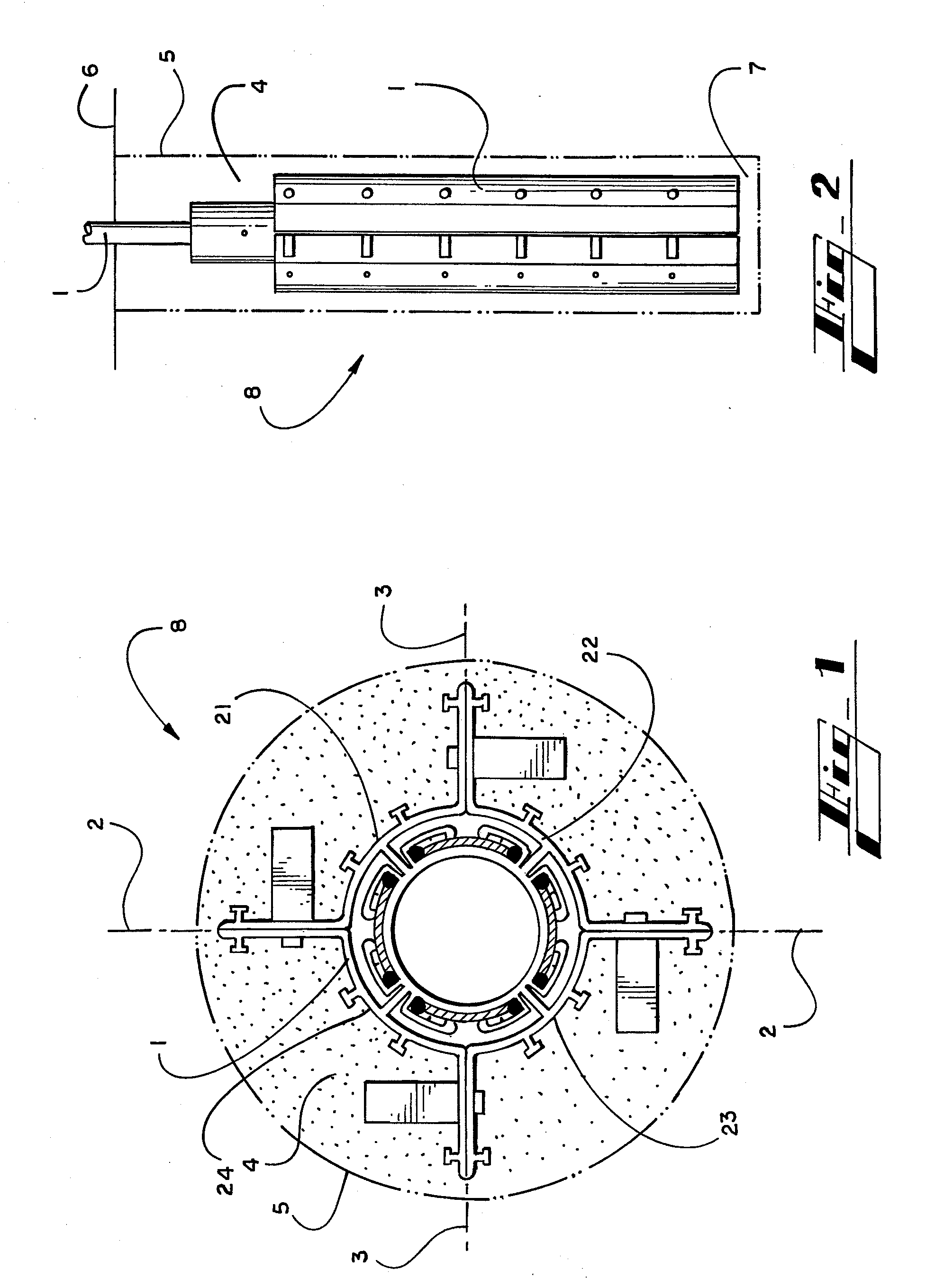
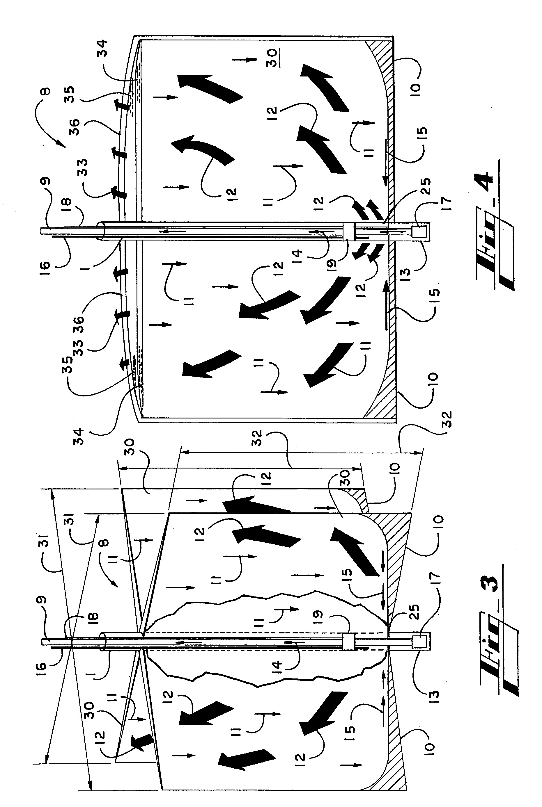
[0038]Several embodiments of the present invention are described below and illustrated in the accompanying drawings. The present invention is a method and apparatus for enhanced recovery of petroleum fluids from the subsurface by injection of steam and a hydrocarbon vaporized solvent in contact with the oil sand formation and the heavy oil and bitumen in situ. Multiple propped hydraulic fractures are constructed from the well bore into the oil sand formation and filled with a highly permeable proppant. Steam, a hydrocarbon solvent, and a non-condensing diluent gas are injected into the well bore and the propped fractures. The injected gas flows upwards and outwards in the propped fractures contacting the oil sands and in situ bitumen on the vertical faces of the propped fractures. The steam condenses on the cool bitumen and thus heats the bitumen by conduction, while the hydrocarbon solvent vapors diffuse into the bitumen from the vertical faces of the propped fractures. The bitumen...


PUM


Abstract

The present invention involves a method and apparatus for enhanced recovery of petroleum fluids from the subsurface by injection of a steam and hydrocarbon vaporized solvent in contact with the oil sand formation and the heavy oil and bitumen in situ. Multiple propped hydraulic fractures are constructed from the well bore into the oil sand formation and filled with a highly permeable proppant. Steam, a hydrocarbon solvent, and a non-condensing diluent gas are injected into the well bore and the propped fractures. The injected gas flows upwards and outwards in the propped fractures contacting the oil sands and in situ bitumen on the vertical faces of the propped fractures. The steam condenses on the cool bitumen and thus heats the bitumen by conduction, while the hydrocarbon solvent vapors diffuse into the bitumen from the vertical faces of the propped fractures. The bitumen softens and flows by gravity to the well bore, exposing fresh surface of bitumen for the process to progressively soften and mobilize the bitumen in a predominantly circumferential, i.e. orthogonal to the propped fracture, diffusion direction at a nearly uniform rate into the oil sand deposit. The produced product of oil and dissolved solvent is pumped to the surface where the solvent can be recycled for further injection.

Description

RELATED APPLICATION[0001]This application is a continuation of copending U.S. patent application Ser. No. 11 / 363,540, filed Feb. 27, 2006, U.S. patent application Ser. No. 11 / 277,308, filed Mar. 27, 2006, U.S. patent application Ser. No. 11 / 277,775, filed Mar. 29, 2006, U.S. patent application Ser. No. 11 / 277,815, filed Mar. 29, 2006, U.S. patent application Ser. No. 11 / 277,789, filed Mar. 29, 2006, U.S. patent application Ser. No. 11 / 278,470, filed Apr. 3, 2006, U.S. patent application Ser. No. 11 / 379,123, filed Apr. 18, 2006, and U.S. patent application Ser. No. 11 / 379,828, filed Apr. 24, 2006.TECHNICAL FIELD[0002]The present invention generally relates to enhanced recovery of petroleum fluids from the subsurface by the injection of steam in the oil sand formation contacting the viscous heavy oil and bitumen in situ, and more particularly to a method and apparatus to extract a particular fraction of the in situ hydrocarbon reserve by controlling the access to the in situ bitumen, ...

Claims


Application Information

Patent Timeline
Patent Type & Authority Applications(United States)
IPC IPC(8): E21B43/24E21B43/26
CPCE21B43/26
Inventor HOCKING, GRANT
Owner GEOSIERRA
Why Eureka
Try Eureka