Unlock instant, AI-driven research and patent intelligence for your innovation.
Antenna and radio communication apparatus
Inactive Publication Date: 2009-06-11
MURATA MFG CO LTD
View PDF7 Cites 11 Cited by
Summary
Abstract
Description
Claims
Application Information
AI Technical Summary
This helps you quickly interpret patents by identifying the three key elements:
Problems solved by technology
Method used
Benefits of technology
[0018]According to this disclosure, a branch electrode shorter than a non-feeding radiation electrode is formed so as to extend from the non-feeding radiation electrode toward the feeding radiation electrode, whereby capacitance generated between this branch electrode and the feeding radiation electrode increases the strength of coupling of harmonic resonances of the non-feeding radiation electrode and the feeding radiation electrode, whereby a return loss in an operating frequency band that is generated by a multi-resonance of harmonic resonances can be reduced.
[0019]In addition, by forming a spiral slit in each of a feeding radiation electrode and a non-feeding radiation electrode, which extend two-dimensionally, a harmonic resonant frequency can be set to a desired frequency while maintaining a fundamental resonant frequency to be substantially constant. Even if there is a reduction of the amount of coupling of harmonic resonances generated by the feeding radiation electrode and the non-feeding radiation electrode, caused by increasing the length of the slit in order to lower the harmonic resonant frequency, a desired return loss characteristic at the harmonic resonant frequency can still be obtained by providing the branch electrode. Thus, flexibility of combining the fundamental wave resonant frequency and the harmonic resonant frequency is enhanced.
Problems solved by technology
However, depending on a combination of a resonant frequency of a fundamental wave and a resonant frequency of a harmonic, matching is frequently not established at the resonant frequency of the harmonic.
Accordingly, an optimal return loss may not be obtained.
Accordingly, the amount of coupling of harmonic resonances between the feeding electrode and the non-feeding electrode is reduced, so that a problem occurs in that a desired gain cannot be obtained since a return loss at a harmonic resonant frequency is large.
Method used
Image
Click on the blue label to locate the original text in one second.
Reading with bidirectional positioning of images and text.
Examples
first embodiment
[0035]An antenna according to a first embodiment and a radio communication apparatus will be described with reference to FIGS. 2A, 2B, 3A and 3B.
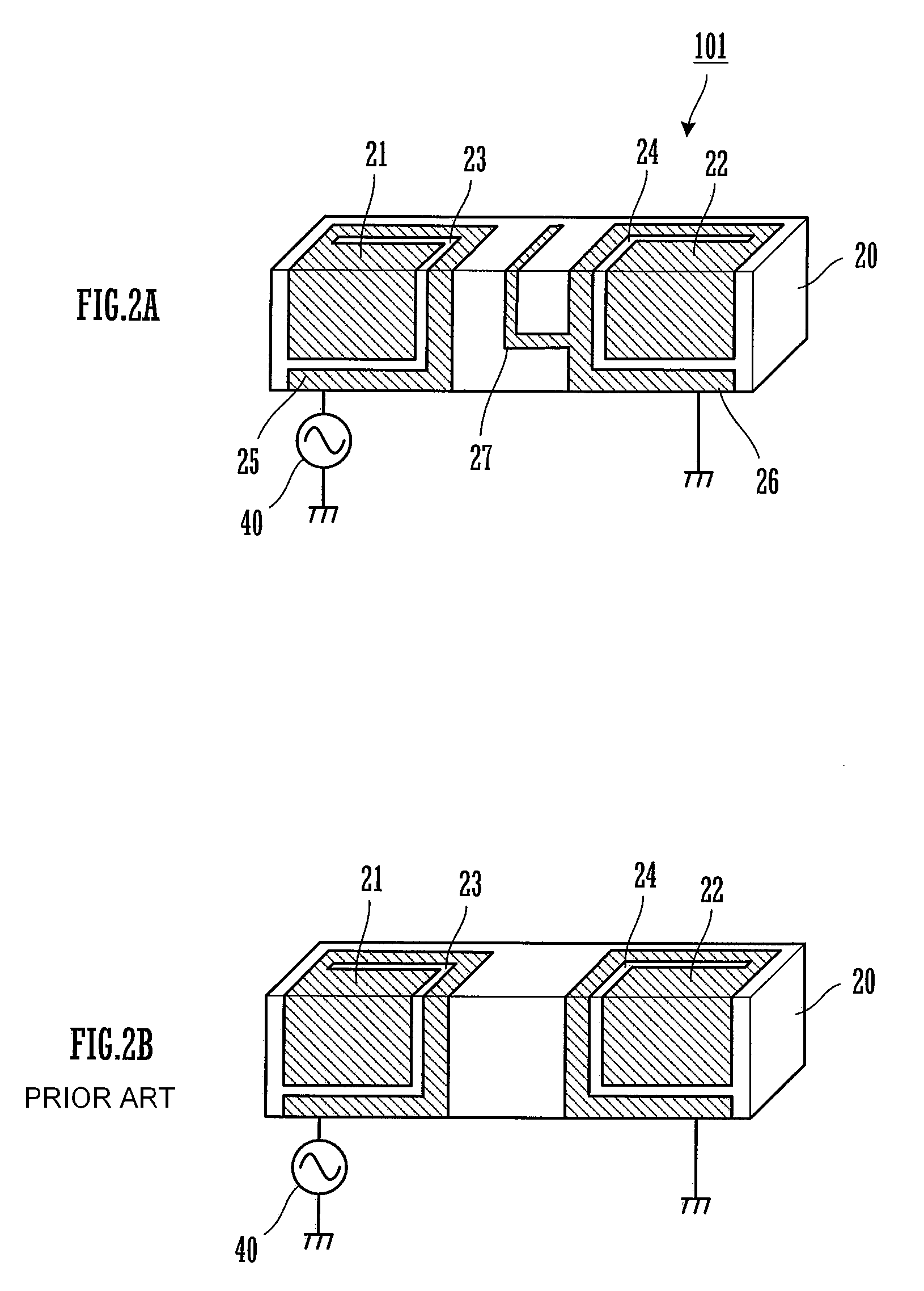
[0036]FIG. 2A is a perspective view of the antenna according to the first embodiment, and FIG. 2B is a perspective view of an antenna as a comparative example therefor.
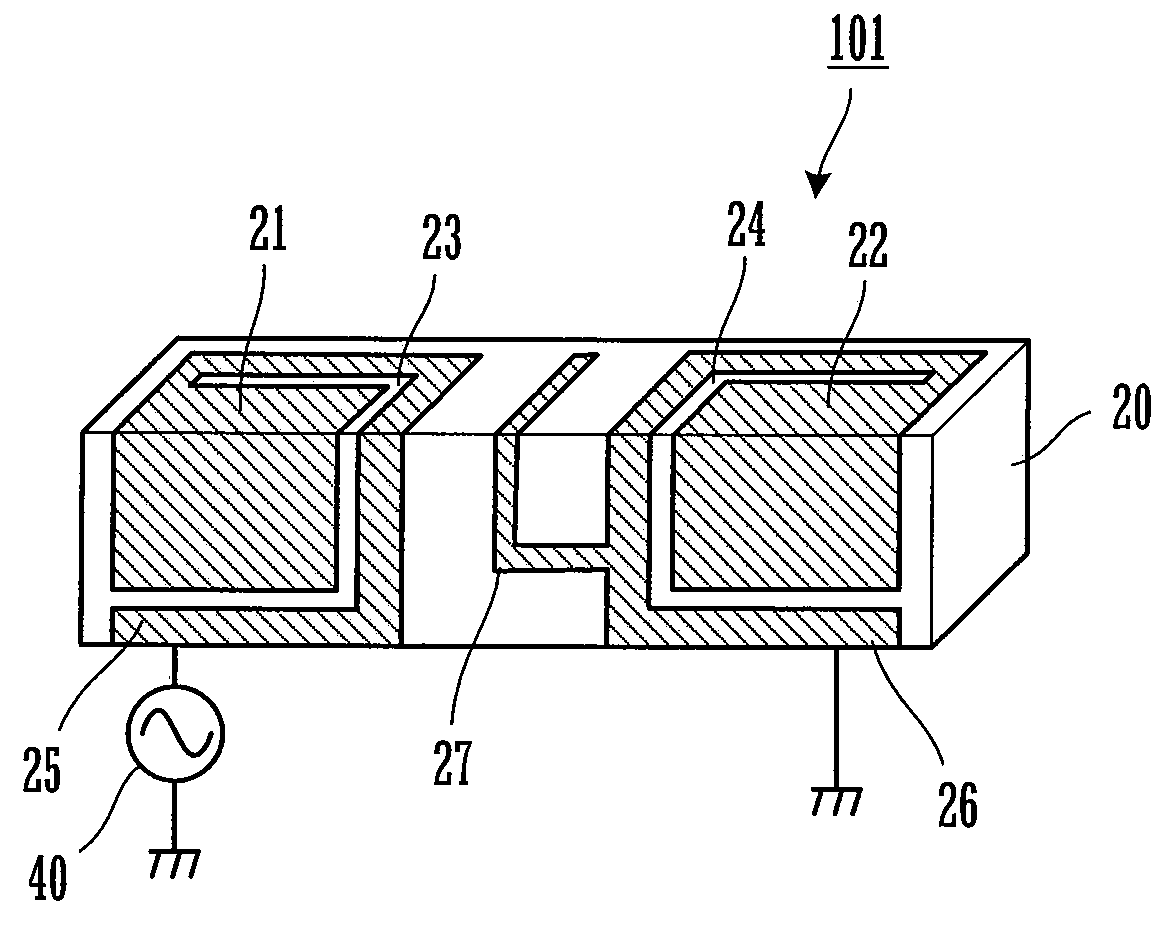
[0037]As shown in FIG. 2A, the antenna 101 according to the first embodiment has a feeding radiation electrode 21 and a non-feeding radiation electrode 22 that each two-dimensionally extend from the front side surface (as seen in the figure) to a top surface of a parallelepiped dielectric base 20. A material of the dielectric base 20 is a compound dielectric material including a dielectric inorganic filler and an organic polymer material, or a combination of a dielectric material and a magnetic material.
[0050]FIG. 4 is a plan view of an antenna 102 according to a second embodiment.
[0051]Although, in the first embodiment, the various types of electrodes are formed on two sides of a parallelepiped dielectric base, in the second embodiment, the electrodes are formed on a substrate. In FIG. 4, on a top surface of a substrate 30, a feeding radiation electrode 31 and a non-feeding radiation electrode 32 that extend two-dimensionally are provided. In the feeding radiation electrode 31 and the non-feeding radiation electrode 32, spiral slits 33 and 34 are respectively formed. The slit 33 formed in the feeding radiation electrode 31 extends from a feeding end 35 in an inward direction, and the slit 34 formed in the non-feeding radiation electrode 32 extends from a ground end 36 in an inward direction.
[0052]A branch electrode 37 is formed from the non-feeding radiation electrode 32 toward the side of the feeding radiation electrode 31. In this example, the branch electrode 37 is formed so as...
third embodiment
[0058]A radio communication apparatus such as a cellular phone is configured in the following manner by using the antennas shown in the first and second embodiments.
[0059]For example, in the case of using the antenna 101 shown in FIG. 2, a radio communication circuit including a radio-frequency generating and feeding means 40 is provided on a circuit board, and a non-ground region is provided at an end of the circuit board (not shown). The antenna 101 is surface-mounted in the non-ground region. This makes it possible to configure a cellular phone for CDMA800 / 2000.
[0060]In addition, in the case of using the antenna 102 shown in FIG. 4, the antenna 102 including the substrate 30 is surface-mounted in the non-ground region of the circuit board (not shown), or each pattern of the antenna 102 is directly formed on the circuit board without being formed on a substrate 30.
PUM
Abstract
A feeding radiationelectrode and a non-feeding radiationelectrode are provided extending from a front side surface to top surface of a dielectric base. In the feeding radiationelectrode, a slit that extends from a feeding end in an inward direction is formed, and, in the non-feeding radiation electrode, a slit that extends from a ground end in an inward direction is formed. In addition, on the non-feeding radiation electrode, a branch electrode is formed so as to extend toward the side of the feeding radiation electrode. With this configuration, gain is obtained in two frequency bands by using a multi-resonance of fundamental wave resonances and harmonic resonances generated by the feeding radiation electrode and the non-feeding radiation electrode, and a good return loss characteristic caused by coupling of harmonic resonances is provided. In other embodiments, the feeding and non-feeding radiation electrodes may be formed on a flat substrate, or directly on a circuit board.
Description
CROSS-REFERENCE TO RELATED APPLICATIONS[0001]This is a continuation under 35 U.S.C. § 111(a) of PCT / JP2008 / 052516 filed Feb. 15, 2008, and claims priority of JP2007-087106 filed Mar. 29, 2007, both incorporated by reference.BACKGROUND[0002]1. Technical Field[0003]This disclosure relates to an antenna for use in a radio communication apparatus such as a mobile communication apparatus, and a radio communication apparatus provided with the antenna.[0004]2. Background Art[0005]Patent Documents 1 and 2 disclose antennas for use in plural frequency bands in radio communication apparatuses such as terminal devices (cellular phones) of a cellular phone system. FIG. 1 is a perspective view of the antenna described in Patent Document 1. In FIG. 1, a radiation electrode 12, and non-feeding electrodes 13 and 14 are formed on a top surface of a dielectric base 11. In addition, a ground electrode 15 is formed on substantially the entirety of a bottom surface of the dielectric base 11 so that an e...
Claims
Application Information
Patent Timeline
Application Date:The date an application was filed.
Publication Date:The date a patent or application was officially published.
First Publication Date:The earliest publication date of a patent with the same application number.
Issue Date:Publication date of the patent grant document.
PCT Entry Date:The Entry date of PCT National Phase.
Estimated Expiry Date:The statutory expiry date of a patent right according to the Patent Law, and it is the longest term of protection that the patent right can achieve without the termination of the patent right due to other reasons(Term extension factor has been taken into account ).
Invalid Date:Actual expiry date is based on effective date or publication date of legal transaction data of invalid patent.