Blade disk seal

a blade disk and seal technology, applied in the direction of liquid fuel engines, vessel construction, marine propulsion, etc., can solve the problems of engine failure, disk failure, disk cracking, etc., and achieve the effect of reducing the stress level of the disk assembly

Inactive Publication Date: 2009-06-11
ALSTOM TECH LTD
View PDF4 Cites 31 Cited by
  • Summary
  • Abstract
  • Description
  • Claims
  • Application Information

AI Technical Summary

Benefits of technology

[0005]Embodiments of the present invention are directed towards a system and method for, among other things, reducing stress levels in a disk assembly while providing a seal between a portion of the disk and one or more blades for a gas turbine engine.
[0006]The present invention provides embodiments for a disk assembly of a gas turbine engine in which a seal plate is secured thereto in order to prevent leakage of cooling air that is directed to cool a blade installed in the disk. The assembly has a disk with generally axially extending slots for receiving one or more blades. In one embodiment, each blade in the disk has a tang that extends radially inward, and one or more seal plates positioned to receive and engage the tang. The tang of the blade is secured to a seal plate by a fastener.
[0008]In yet another embodiment, a seal plate capable of minimizing cooling fluid leakage between a disk and one or more blades is provided. In one embodiment, the seal plate has generally parallel first and second members that are connected by a leg with the first and second members each having through holes for receiving a fastener. The first and second members are spaced apart a distance sufficient to receive a blade tang therebetween.

Problems solved by technology

Such large stress concentrations have been known to exceed material capabilities at the disk operating temperatures and have led to cracking within the disk, failure of the disk, and engine failure.

Method used


Image

  • Blade disk seal
  • Blade disk seal
  • Blade disk seal

Examples


Embodiment Construction

[0027]The subject matter of the present invention is described with specificity herein to meet statutory requirements. However, the description itself is not intended to limit the scope of this patent. Rather, the inventors have contemplated that the claimed subject matter might also be embodied in other ways, to include different components, combinations of components, steps, or combinations of steps similar to the ones described in this document, in conjunction with other present or future technologies.

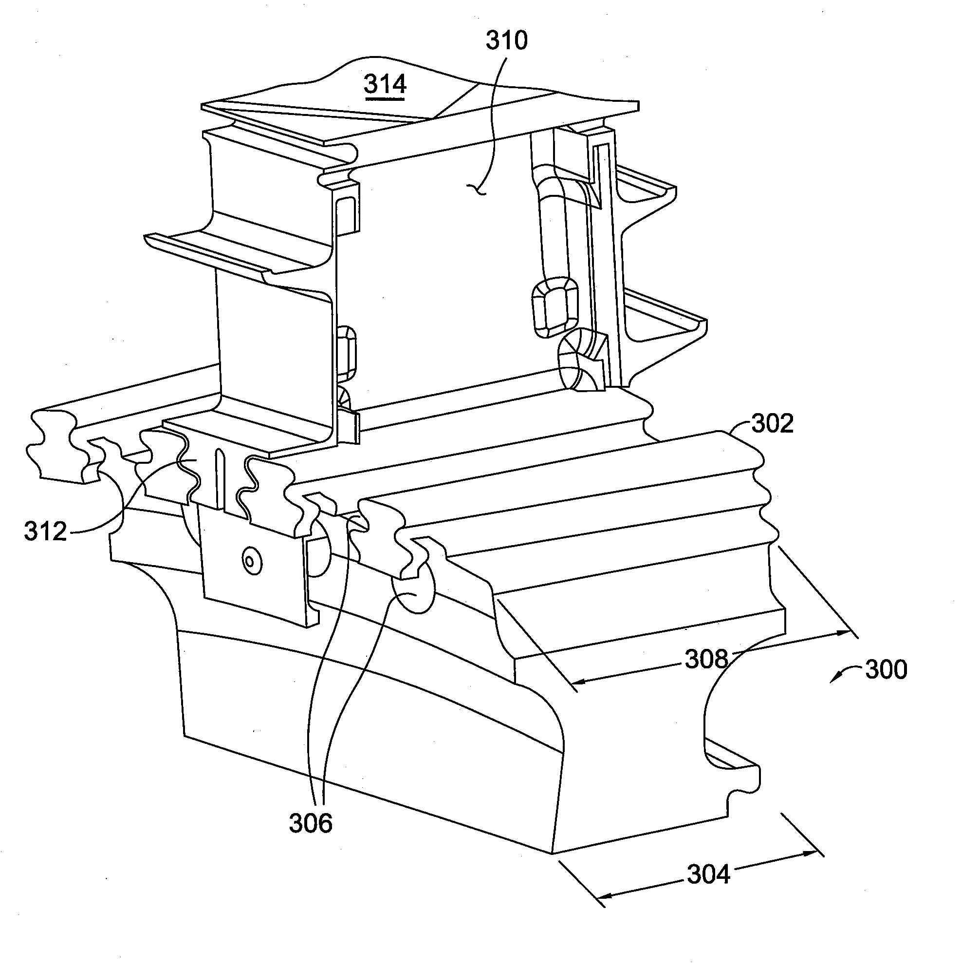
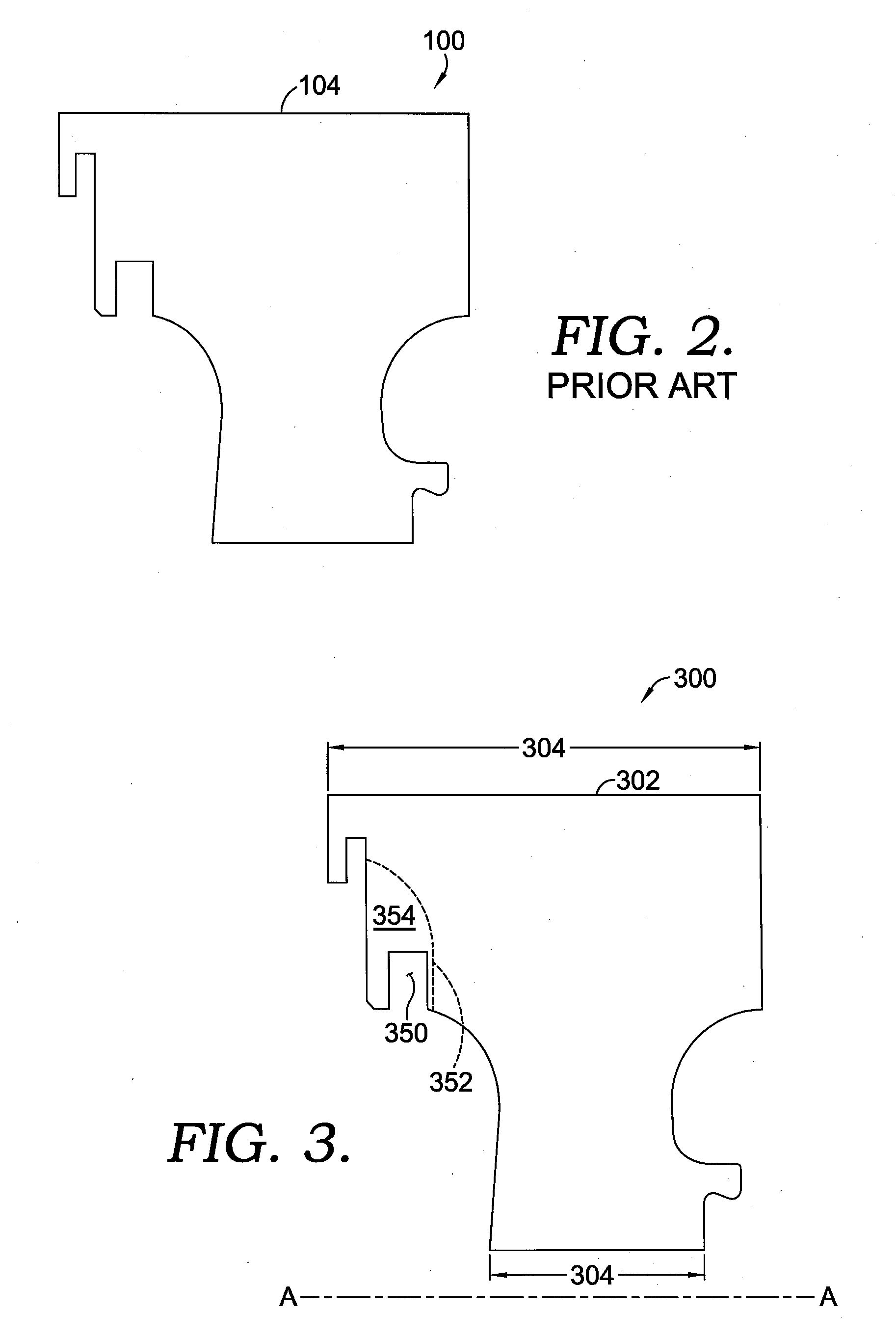
[0028]Referring initially to FIG. 3, a portion of a disk 300 is depicted in cross section. The disk 300 has an outer circumferentially extending surface 302 and a center axis A-A. In operation, the disk 300 rotates about the center axis A-A. Depending on the engine geometry, the disk 300 can vary in a thickness 304. This thickness 304 can also vary for each stage of an engine. The disk 300 comprises a plurality of blade slots 306, as shown in FIGS. 4 and 5, with the blade slots 306 ...


PUM


Abstract

An apparatus and method are disclosed for reducing the operating stresses in a disk of a gas turbine engine while providing a seal plate to minimize leakage of a cooling fluid from the blades positioned in the disk. The seal plate is fastened to a tang of one or more of the blades. The seal plate configuration can be utilized with a newly manufactured disk and blades or with a modification to an existing disk and blades. The disk, blade, and seal plate configuration reduce operating stresses in the disk that are caused by mechanical loading on the disk by one or more rotating blades.

Description

CROSS-REFERENCE TO RELATED APPLICATIONS[0001]This application claims priority to the Provisional Patent Application having Ser. No. 61 / 012,475 and filed on Dec. 10, 2007.TECHNICAL FIELD[0002]The present invention relates to gas turbine engines. More particularly, embodiments of the present invention relate to an apparatus and method for reducing stress in a blade disk while minimizing leakage of cooling fluids directed towards one or more blades.BACKGROUND OF THE INVENTION[0003]Gas turbine engines operate to produce mechanical work or thrust. Specifically, land-based gas turbine engines typically have a generator coupled thereto for the purposes of generating electricity. A gas turbine engine comprises a number of components including a compressor section which has a series of rotating compressor blades. The compressor, which receives air from an engine inlet, passes the air through the compressor, where the pressure of the air increases. The compressed air is then directed into one...

Claims


Application Information

Patent Timeline
Patent Type & Authority Applications(United States)
IPC IPC(8): F01D5/30
CPCF01D5/3007F05D2260/94F01D11/006
Inventor STROHL, J. PAGEPETETT, ANTHONYKRAFT, ROBERT J.
Owner ALSTOM TECH LTD
Why Eureka
Try Eureka