Pvd - vacuum coating unit

a vacuum coating and vacuum technology, applied in vacuum evaporation coating, plasma technique, coatings, etc., to achieve the effect of low residual stress, low spacing, and high layer quality

Inactive Publication Date: 2009-06-11
OERLIKON TRADING AG TRUEBBACH
View PDF5 Cites 11 Cited by
  • Summary
  • Abstract
  • Description
  • Claims
  • Application Information

AI Technical Summary

Benefits of technology

[0045]Considerably preferred is, however, a disposition in which the substrates are deposed such that they are stationarily positioned on or within the substrate carrier. The cutting edges, in particular if there are several for each substrate on its periphery, are thereby opposite the one or the other opposing source, each preferably assigned to the corresponding material flow of this source, depending on which edge or which edge portion is exposed in direct line of sight opposite the particular cathode of the source. In certain cases edge portions can also be acted upon from both sides depending on the position of the substrates in the substrate carrier arrangement. It is of advantage if the laminar substrates are deposed such that they are positioned at right angles one next to the other with respect to the laminar substrate carrier, advantageously at a minimal spacing from one another. In certain cases the substrates can be deposed at a slight inclination with respect to the plane of the subst

Problems solved by technology

A further problem comprises realizing a new configuration which combines PVD coating sources with substrate mountings such that similar substrate mountings in laminar shape can be u

Method used


Image

  • Pvd - vacuum coating unit
  • Pvd - vacuum coating unit
  • Pvd - vacuum coating unit

Examples


Embodiment Construction

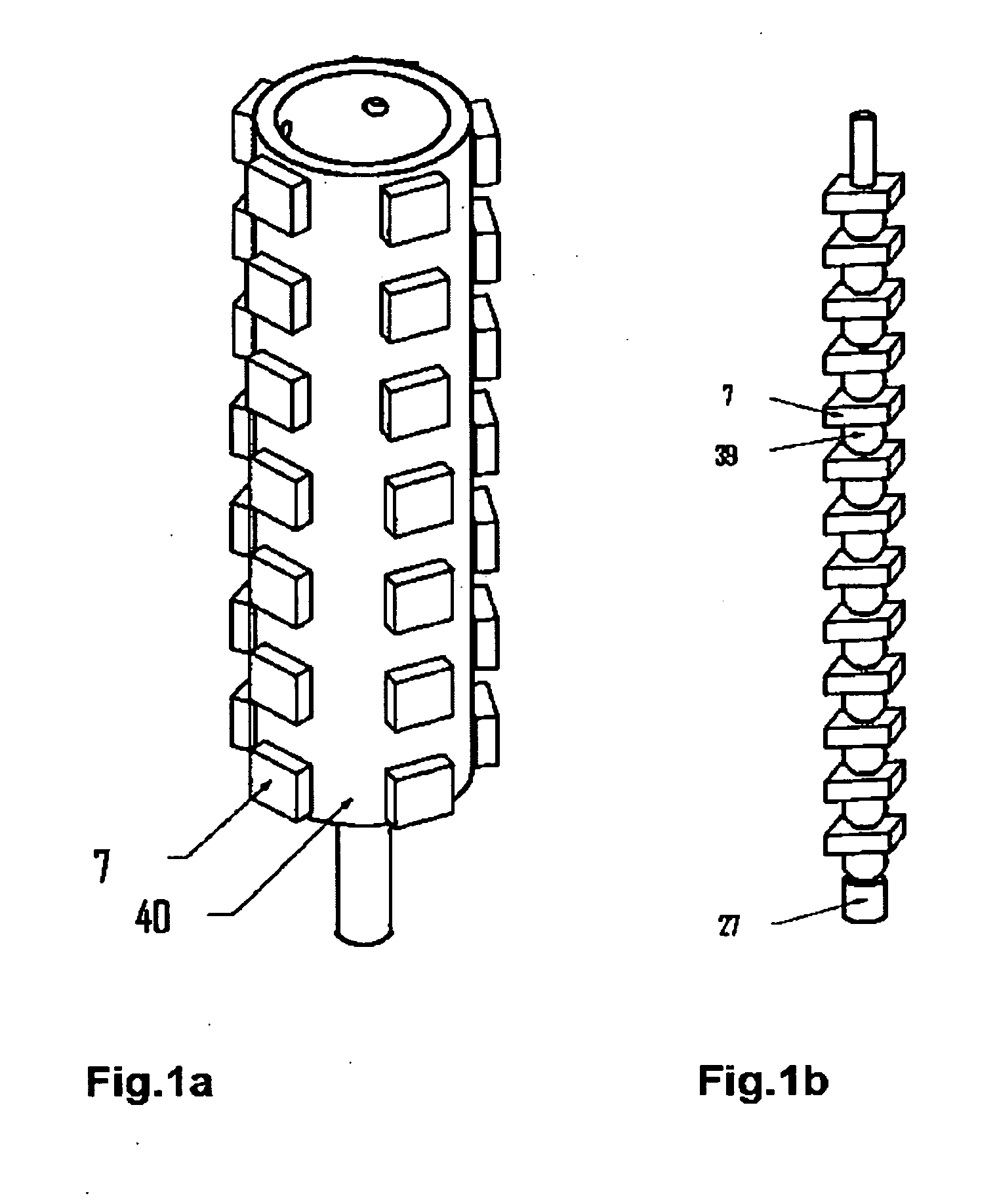
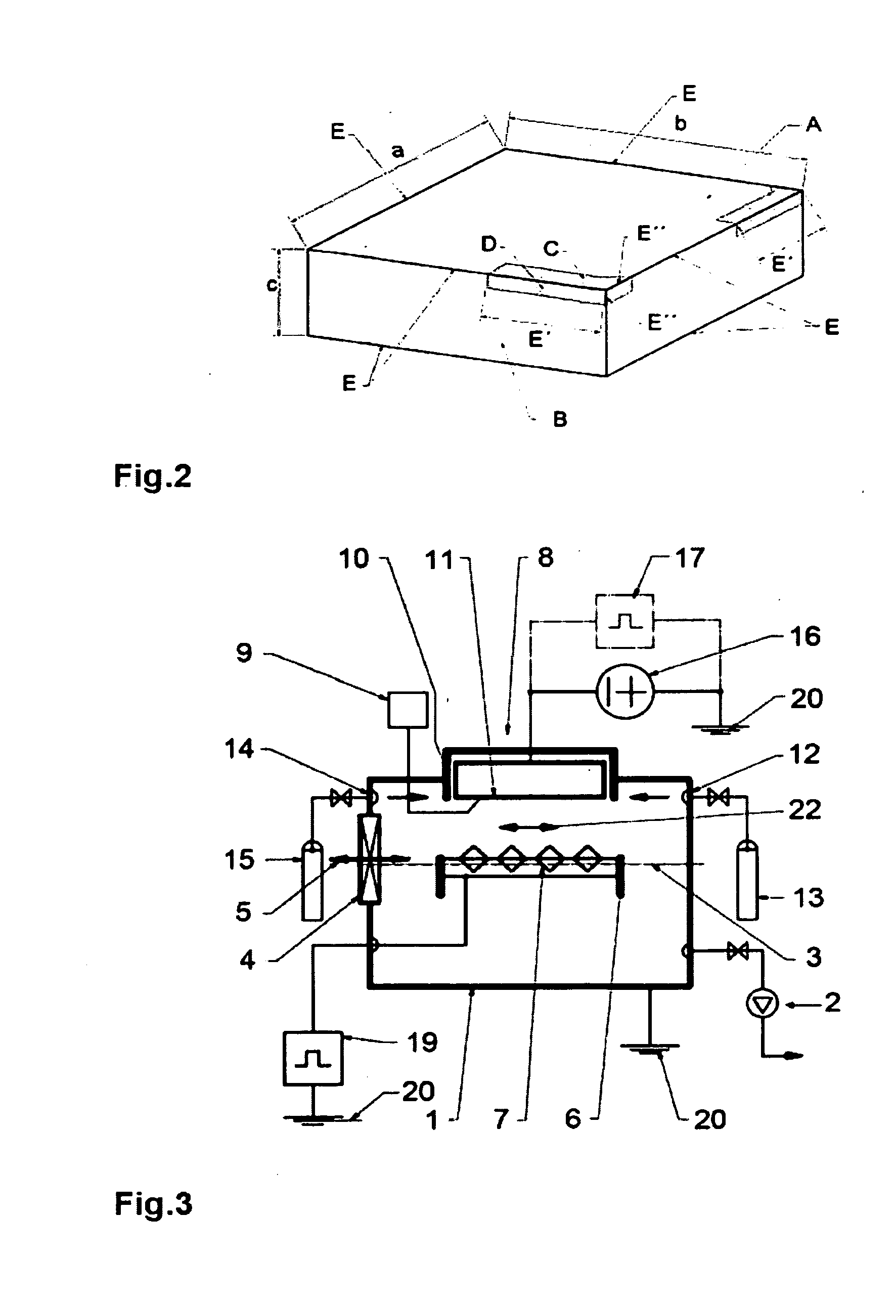
[0076]The substrates to be coated have substantially a two dimensional form or a laminarly extended form. This means that the side lengths a and b are substantially greater than the third side length c of the body, as is the case in the preferred cutting tools 7 to be coated, the indexable cutter inserts, and as is depicted schematically and by example in FIG. 2. The goal of the coating is to coat the cutting edges E with the associated flank face B and the rake face A. In such a cutting tool conventionally only a portion of edge lengths with the associated side faces formed on the tool is utilized in the cutting process. This portion is denoted as the active cutting edge E′ and lies within 50% or even only 30% of the total length available on the workpiece of a cutting edge.

[0077]The dimensions E″ of edge E in the flank face B, where the flank face wear D occurs, and from the edge E into the rake face A, where the crater wear occurs, are in the range of 50 μm to 5.0 mm and must als...


PUM

PropertyMeasurementUnit
Lengthaaaaaaaaaa
Lengthaaaaaaaaaa
Fractionaaaaaaaaaa

Abstract

A vacuum coating unit includes a reactive gas inlet, at least one PVD coating source with a laminar cathode and a substrate carrier containing a multiplicity of substrates. The substrate carrier forms a two dimensional horizontal extent, and the carrier is between at least two PVD coating sources. The substrates are cutting tools with at least one cutting edge in their peripheral margin region, which are distributed in a plane of the two dimensional extent of the substrate carrier. The substrate carrier is in a horizontal plane in the vacuum process chamber spaced between the laminar cathodes of the PVD coating sources and positioned such that at least a portion of each of the at least one cutting edge includes an active cutting edge and this active cutting edge is oriented opposite at least one of the cathodes of the PVD coating sources exposed at any time along a line of sight.

Description

FIELD AND BACKGROUND OF THE INVENTION[0001]The invention relates to a vacuum coating unit and furthermore to a method for the simultaneously coating of several planiform or laminar substrates with a hard material coating.[0002]There are PVD vacuum coating units with substrate mountings for tools such as machine tools, cutting tools like drills, cutting inserts, etc., which are optimized primarily for rotationally symmetric workpiece geometries, such as, for example, for shaft tools with different dimensions. Examples of this are production systems by OC Oerlikon Balzers AG Liechtenstein, such as the unit of type RCS described in EP 1 186 681 A1 and the unit of type BAI 1200 described in detail in EP 0 886 880 B1. Typical rotating mountings for indexable cutter inserts (cutting tools) utilized in these production systems are depicted in FIG. 1a and 1b. The indexable cutter inserts 7 can herein be fastened, for example, on drum-like magnetic workpiece carriers 40 or be disposed on rod...

Claims


Application Information

Patent Timeline
IPC IPC(8): C23C14/28C23C16/00
CPCC23C14/325C23C14/505C23C14/50
Inventor RAMM, JUERGENWOHLBAB, CHRISTIAN
Owner OERLIKON TRADING AG TRUEBBACH
Why Eureka
Try Eureka