Outlet duct of battery system for hybrid electric vehicle
- Summary
- Abstract
- Description
- Claims
- Application Information
AI Technical Summary
Benefits of technology
Problems solved by technology
Method used
Image

Examples
Embodiment Construction
[0030]Reference will now be made in detail to the preferred embodiments of the present invention, examples of which are illustrated in the drawings attached hereinafter, wherein like reference numerals refer to like elements throughout. The embodiments are described below so as to explain the present invention by referring to the figures.
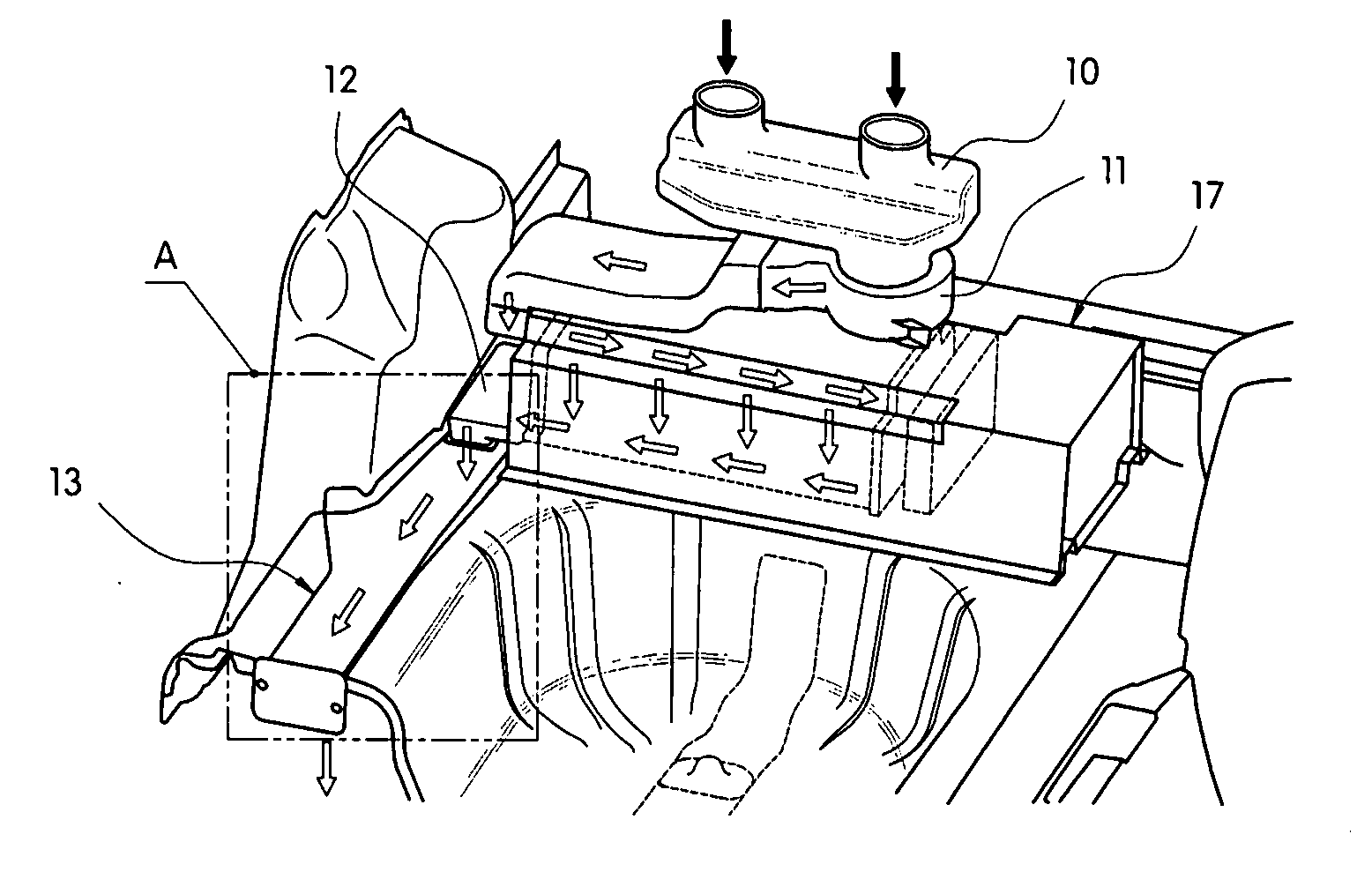
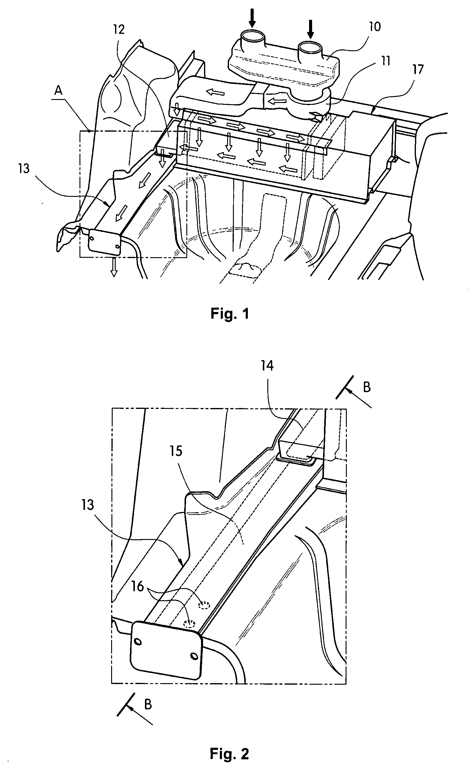
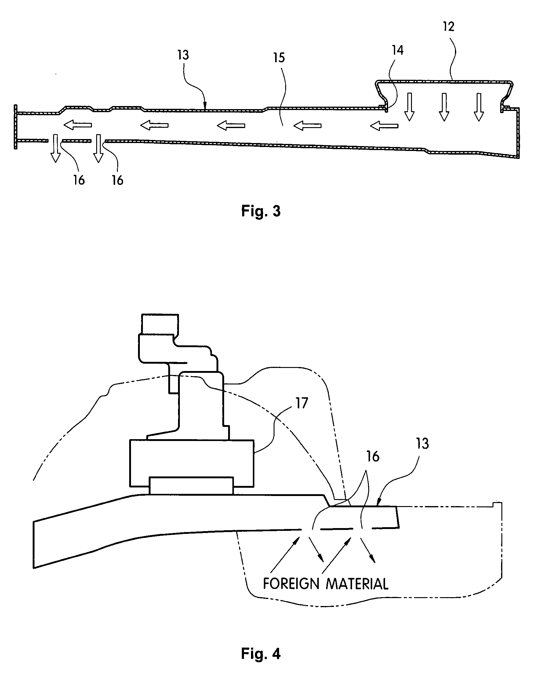
[0031]As shown in FIGS. 1 to 4, an outlet duct 12 for discharging air exhausted from a battery system 17 of an HEV to the outside has a structure in which a side member 13 of a rear filler assembly disposed on one side of the battery system 17 is utilized as it is. Accordingly, the length of the discharge path of air can be greatly reduced, compared with the conventional discharge path extending to the rear portion of the trunk, and thus it is possible to reduce the overall length of the outlet duct 12, thus effectively discharging the air.
[0032]For this, the battery system 17, in which an inlet duct 10 for the inflow of indoor air and a blower 11 f...
PUM
 Abstract
Description
Claims
Application Information