
Shockwave fabrication of thermoelectric materials

a thermoelectric material and shock wave technology, applied in the manufacture/treatment of thermoelectric devices, ultra-high pressure processes, etc., can solve the problems of limited interparticle bonding in prior art methods that use powder compaction, and achieve the effect of reducing the mean free path of phonons, small crystalline structure, and preserving the ability for electron transmission

Inactive Publication Date: 2009-06-18
TXL GROUP
View PDF13 Cites 4 Cited by
  • Summary
  • Abstract
  • Description
  • Claims
  • Application Information

AI Technical Summary

Benefits of technology

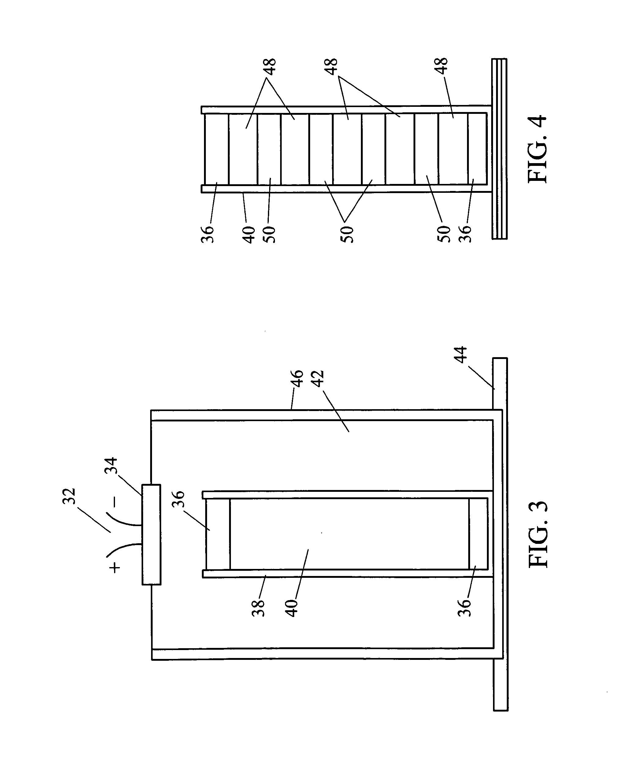
[0017]In order to reduce the mean free path of phonons it is desirable for the semiconductor thermoelectric to have small crystalline structure, that is, many grain boundaries that would serve to block phonon transmission while preserving the ability for electron transmission. In this sense, we desire a “pseudo-glassy” material. One way to accomplish this is through shock wave consolidation of a powder mixture. As contrasted with powder compaction and sinterning techniques, consolidation allows complete particle to particle bonding, thus producing a monolith of homogeneous properties. Shock consolidation requires the very rapid collapse of the gaps between the powder particles as well as the rapid deposition of energy at the particle surfaces. These processes must be close to adiabatic. The ultra rapid deformation and energy deposition is accomplished in time durations of microseconds by the passage of an explosively produced shock wave. The amplitude of the shock wave has to be sufficient to bond the powders but should not be so high as to produce extensive melting and cracking on subsequent reflections. The correct choice of explosive material and experimental geometry can ensure an acceptable result.
[0019]Prior art approaches to the preparation of thermoelectric materials using melts will exhibit a polycrystalline structure that does nothing to inhibit phonon transport. Prior art approaches that use powder compaction will have limited interparticle bonding. Accordingly, the present invention has the following objects and advantages for the manufacture of thermoelectric materials:a. It maximizes interparticle bonding and thereby enhances electrical conductivity;b. Thermoelectric materials are produced adiabatically, discouraging the formation of crystalline structures;c. It results in a reduced lattice thermal conductivity; andd. It yields an improved performance thermoelectric material.

Problems solved by technology

Prior art approaches that use powder compaction will have limited interparticle bonding.

Method used


Image

  • Shockwave fabrication of thermoelectric materials
  • Shockwave fabrication of thermoelectric materials
  • Shockwave fabrication of thermoelectric materials

Examples


Embodiment Construction

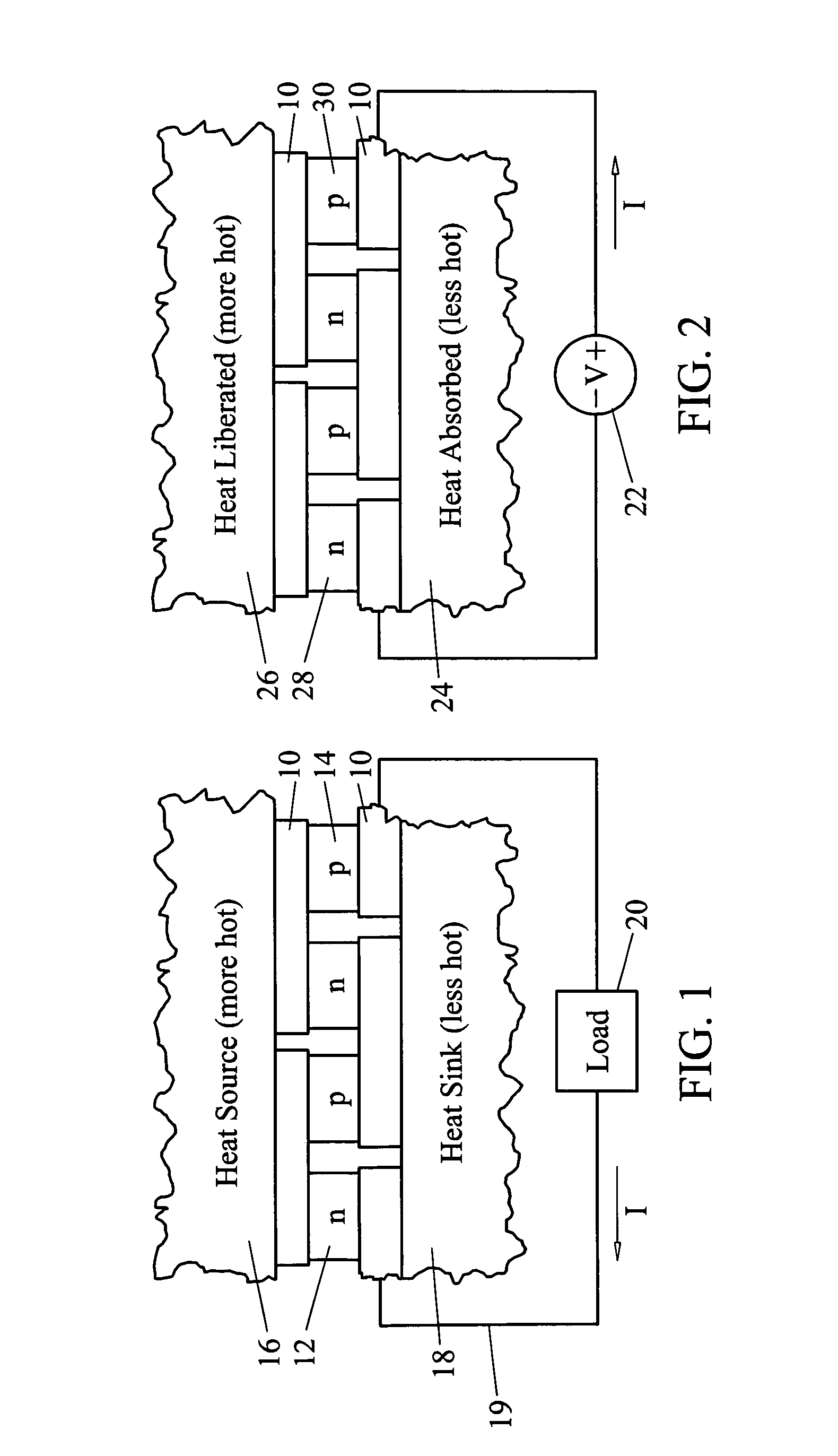
[0047]FIG. 1 depicts the side view of a typical thermoelectric generator. The generator is constructed by sandwiching specially chosen n and p type conductor or semiconductor material (the thermoelements) between electrical conductors 10. Although thermoelements may be built using conductors such as bismuth and antimony, higher efficiency thermoelectrics are built using heavily doped semiconductors. The electrical conductors 10 will be chosen to be good conductors of both electricity and heat. When fabricated from a semiconductor material, the n type thermoelement 12 is formed by the introduction of a pentavalent chemical compound so that electrons are the majority carrier. When fabricated from a semiconductor material, the p type thermoelement 14 is formed by the introduction of a trivalent chemical compound so that the majority carriers are holes. When the thermoelectric device is placed between a heat source 16 and a heat sink 18, there is a flow of heat energy from the source 16...


PUM

PropertyMeasurementUnit
Sizeaaaaaaaaaa
Densityaaaaaaaaaa
Ratioaaaaaaaaaa

Abstract

The explosive consolidation of semiconductor powders results in thermoelectric materials having reduced thermal conductivity without a concurrent reduction in electrical conductivity and thereby allows the construction of thermoelectric generators having improved conversion efficiencies of heat energy to electrical energy.

Description

CROSS-REFERENCE TO RELATED APPLICATIONS[0001]This application claims the priority date of U.S. Provisional Patent Application 61 / 007,319, entitled “High efficiency electricity generation from a thermal gradient” which was filed on Dec. 12, 2007. The specifications of that application are incorporated herein by reference.BACKGROUND OF THE INVENTION[0002]1. Field of the Invention[0003]This invention relates to the shockwave fabrication of thermoelectric materials as a means for deriving an enhanced performance. The consolidation of micro and nano-scale powders through explosive means results in a material that impedes thermal energy transmission through lattice vibrations (phonons) without negatively impacting electrical conductivity, the result being an improvement in thermoelectric conversion efficiency.[0004]2. Background of the Invention[0005]Energy is a quantity that has many forms, with electrical energy having the attractive property that it may be easily transmitted through co...

Claims


Application Information

Patent Timeline
IPC IPC(8): B22F3/08
CPCB01J3/08H01L35/34B22F7/08B22F3/08H10N10/01
Inventor RUBIO, EDWARDNEMIR, DAVID CHARLES
Owner TXL GROUP
Learn More