
Circularly polarized omnidirectional in-building signal booster apparatus and method

a booster and building technology, applied in the field of single-feed circularly polarized omnidirectional helical antenna systems, can solve the problems of introducing coverage (fill) and certain safety issues, affecting logistical and cost, and arcing risk in such small elements, so as to improve overall signal power and regulate overall signal power.

Inactive Publication Date: 2009-06-18
SPX CORP
View PDF2 Cites 45 Cited by
  • Summary
  • Abstract
  • Description
  • Claims
  • Application Information

AI Technical Summary

Benefits of technology

[0012]In accordance with yet another embodiment of the present invention, a method is presented for rebroadcasting a signal from a source to a region whereto propagation of the signal is impeded. The method for rebroadcasting includes receiving an electromagnetic signal from a broadcast radio transmission having a first handedness of elliptical polarization and transferring the signal to an amplifier, wherein the amplifier performs the steps of accepting the signal, attenuating out-of-band signal energy, adjusting relative phase of in-band signal frequency components, increasing overall signal power, regulating overall signal power, and furnishing the amplified signal for retransmission. The method further includes applying the received signal to a radio signal emitter having a second handedness of elliptical polarization, and coupling the signal from the emitter to a surrounding region.

Problems solved by technology

High power translates to high voltage, leading to risk of arcing and dielectric breakdown in such small elements.
Large (high gain, multi-element) antennas permit reduction in the total number of transmitter sites needed to serve a region, but can introduce coverage (fill) and certain safety issues.
Small (low gain, few element) antennas may require large numbers of transmitter sites to achieve coverage, aggravating logistical and cost issues.
While very low frequency electromagnetic signals easily penetrate structures (and even sea water to a substantial depth), higher frequencies may be blocked.
Known types of broadcasting facilities are significantly deficient in broadcasting signals within propagation-impeding structures.
Overall systems solutions are significantly lacking: even though a desired signal may exist outside a building in substantially the desired form, such as circular polarization with a good power level, access within the building can be blocked.
Current systems are not capable of reliable delivery of one or more channels of broadcast signals inside a structure, where the structure exhibits an uncontrolled extent of shielding against signals present outside the structure.

Method used


Image

  • Circularly polarized omnidirectional in-building signal booster apparatus and method
  • Circularly polarized omnidirectional in-building signal booster apparatus and method
  • Circularly polarized omnidirectional in-building signal booster apparatus and method

Examples


Embodiment Construction

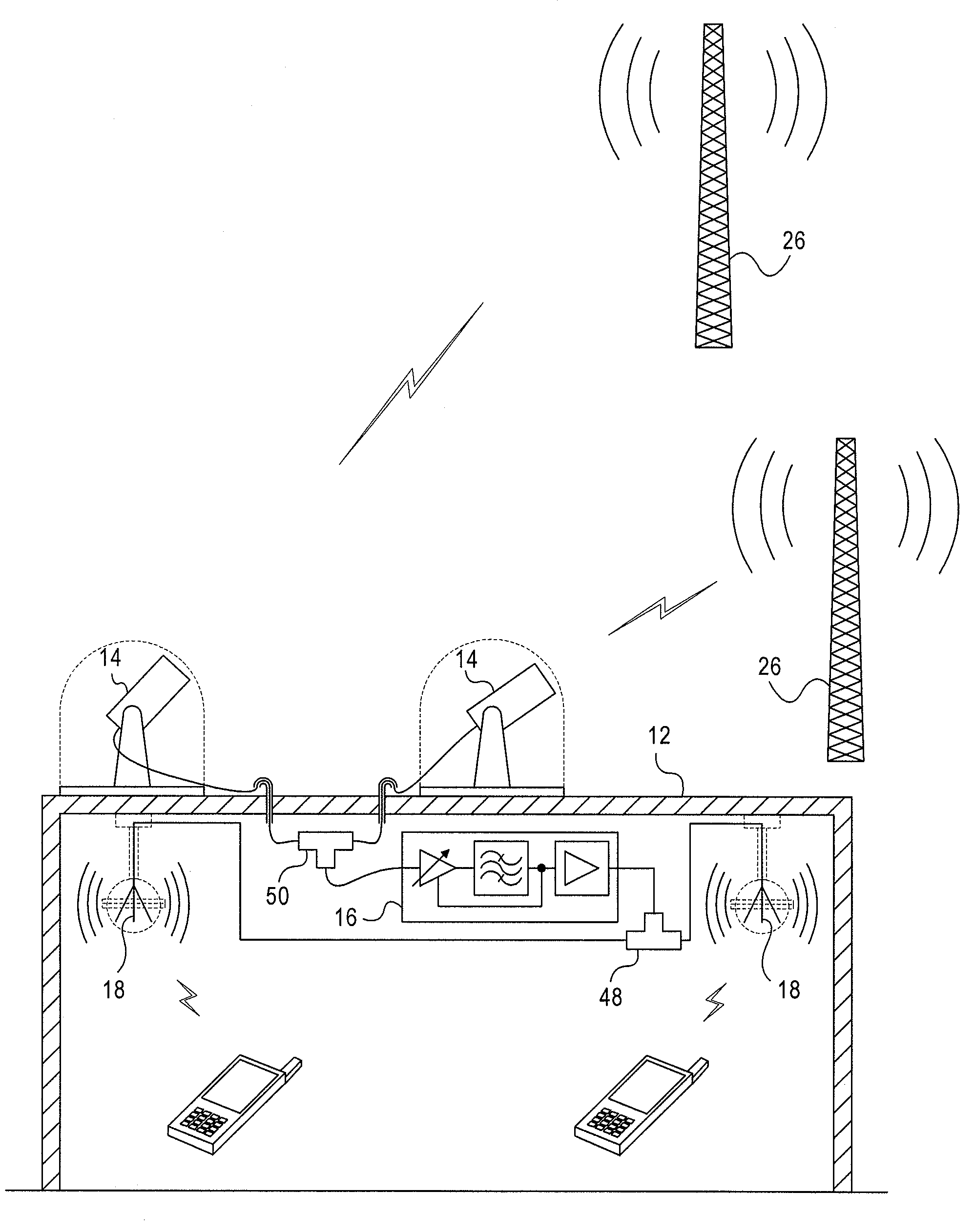
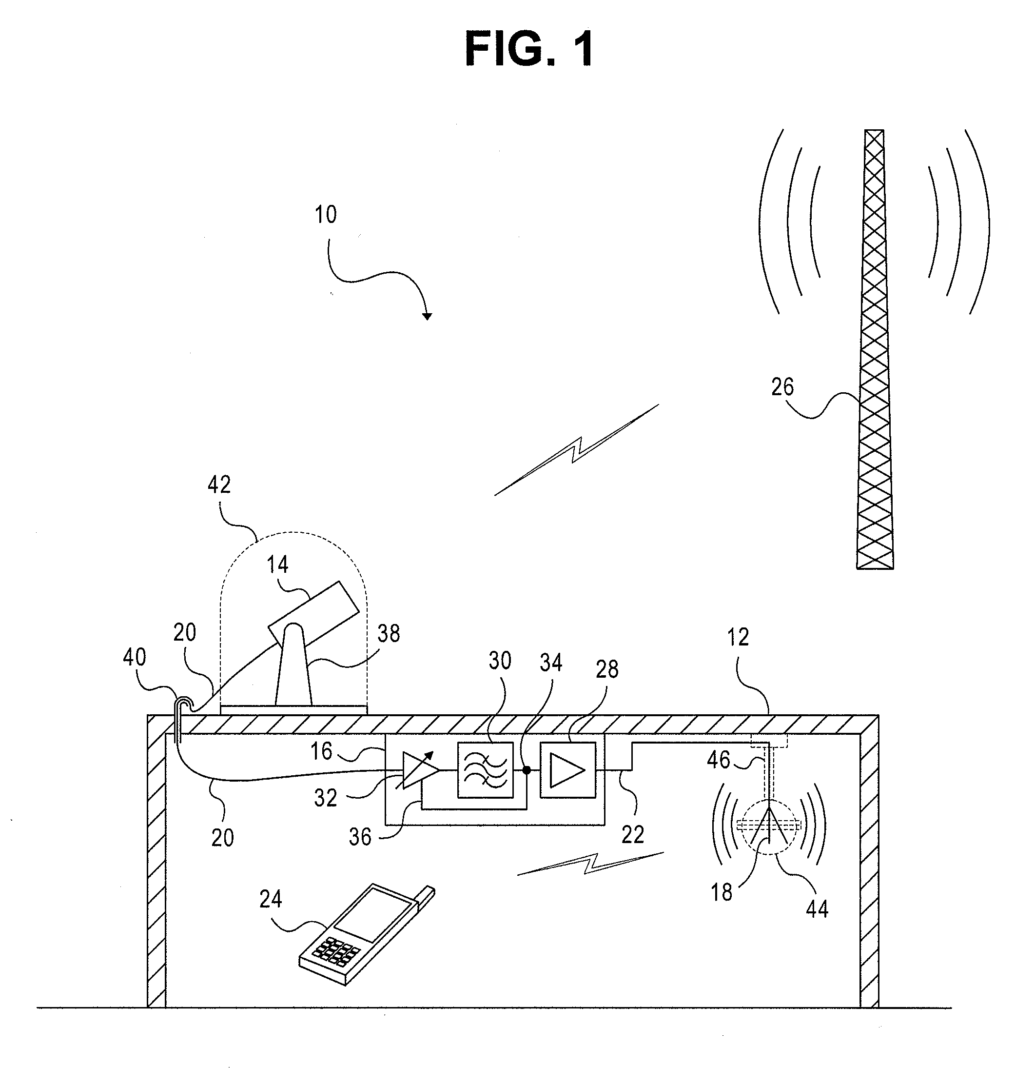
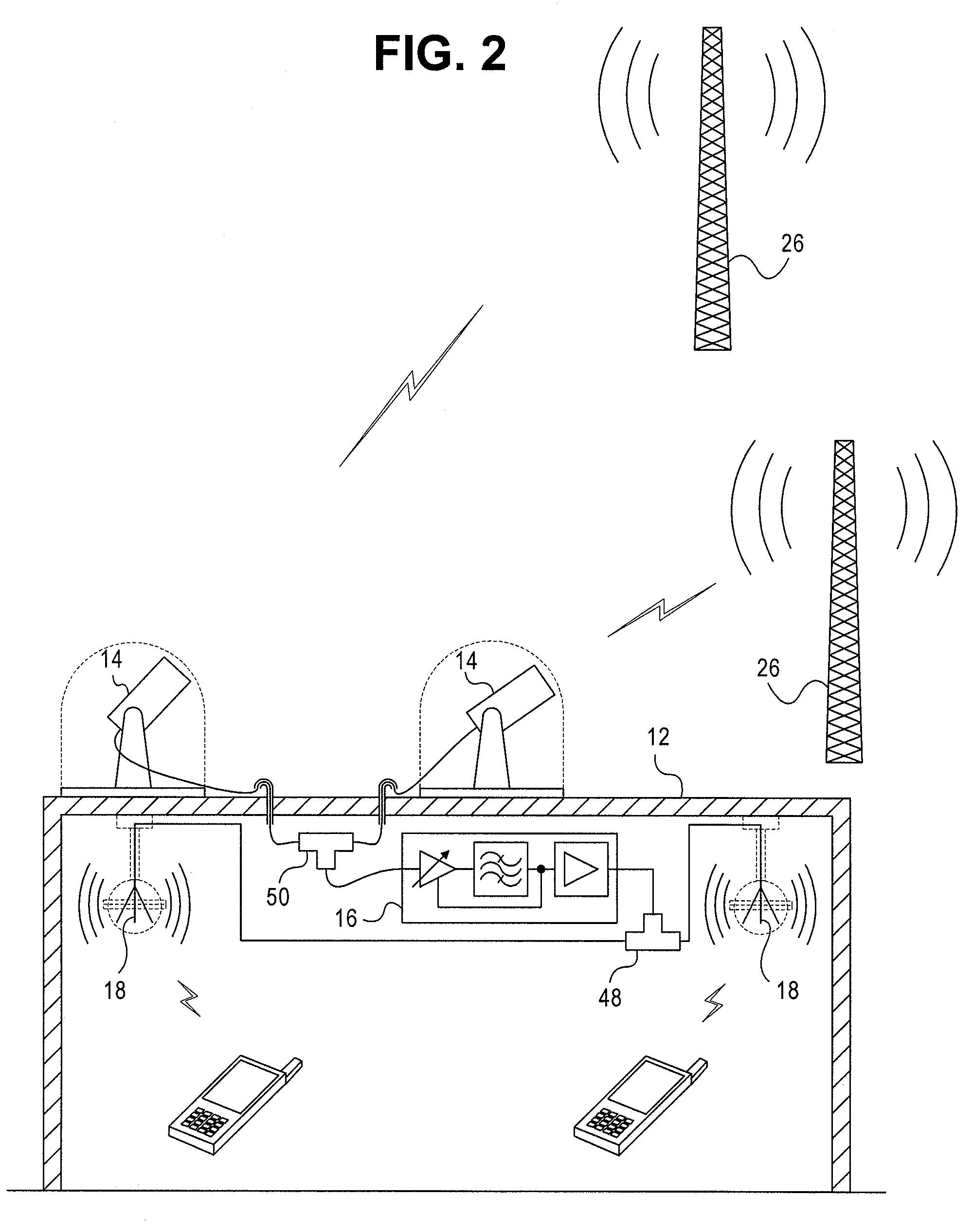
[0024]The invention will now be described with reference to the drawing figures, in which like reference numerals refer to like parts throughout. An embodiment in accordance with the present invention provides rebroadcast inside a signal-attenuating structure of a signal present outside the structure.

[0025]FIG. 1 is a schematic diagram of a system 10 that can reproduce a transmitted signal inside an impeding structure 12 such as a mostly-metal-clad shopping mall. The system 10 includes a receiving antenna 14, an amplifier 16, and a transmitting antenna 18, as well as suitable interconnecting signal lines 20 and 22. It is to be understood that the interconnecting signal lines 20 and 22 in any specific embodiment may be combined or omitted. The system 10 may be used for purposes such as providing digital broadcast video program content for handheld receiving devices 24 within a structure 12.

[0026]The existence of a broadcasting signal source, represented by a radiating tower 26 in FIG...


PUM


Abstract

A rebroadcasting apparatus for mobile media includes a receiving antenna and a transmitting antenna. The signal to be rebroadcast is received with a circularly polarized directional antenna. The transmitting antenna has circular polarization opposite to the polarization of the receiving antenna. Amplifiers and filters may be included between receiving and transmitting antennas to regulate retransmitted signal quality. The transmitting antenna uses one or more bays of quasi-helical dipole radiators excited using manifold feed equipped with tuning paddles. The transmitting antenna may be formed from light-weight sheet metal or other readily mass-produced materials. The transmitting antenna may be housed within an ordinary security camera enclosure or similar radio-transparent housing.

Description

FIELD OF THE INVENTION[0001]The present invention relates generally to radio frequency (RF) electromagnetic signal broadcasting systems. More particularly, the present invention relates to single-feed circularly polarized omnidirectional helical antenna systems for auxiliary broadcasting.BACKGROUND OF THE INVENTION[0002]The background section for U.S. nonprovisional patent application Ser. No. 11 / 826,100 (“the '100 application”), titled “Circularly Polarized Low Wind Load Omnidirectional Antenna Apparatus and Method,” filed Jul. 12, 2007, which is hereby incorporated by reference in its entirety, addresses the opportunity introduced by opening previous television channels in the band from about 700 MHz to 750 MHz for new uses. These uses potentially include at least moderate-power broadcasting directed toward handheld receivers and related technologies and services. Broadcast antennas such as those presented in the '100 application address the requirements for wide-range coverage wi...

Claims


Application Information

Patent Timeline
IPC IPC(8): H04B7/14H01Q9/28H04B1/16H04B15/00
CPCH01Q21/205H04B7/1555H01Q21/29H01Q21/24
Inventor SCHADLER, JOHN L.
Owner SPX CORP
Learn More