
Jet plasma gun and plasma device using the same

Inactive Publication Date: 2009-06-25
IND TECH RES INST
View PDF13 Cites 1 Cited by
  • Summary
  • Abstract
  • Description
  • Claims
  • Application Information

AI Technical Summary

Benefits of technology

[0008]The invention is directed to a jet plasma gun and a plasma device using the same. By way of using an insulating material, the electric arc and abnormal electrical discharge of the plasma are suppressed, and the quality of surface treatment on the substrate is improved.

Problems solved by technology

If the distance between the substrate and the plasma gun is very small and the plasma gun provides high-voltage plasma (for example, during the surface treatment by plasma under an atmospheric environment), mean free path of the particles of the plasma is so small that unexpected collision occurs between particles, resulting in unexpected and uncontrollable abnormal electrical discharge between the plasma gun and the surface of the substrate.
For example, electric arc and hairspring discharge will damage the substrate surface and the plasma device.
The electric arc will damage the jet plasma gun and make metal particles coming off the surface of the plasma nozzle and polluting the substrate.
Because the electric arc and abnormal electrical discharge occur at the opening of the jet plasma gun, the adaptability of plasma in substrate treatment is restricted.

Method used


Image

  • Jet plasma gun and plasma device using the same
  • Jet plasma gun and plasma device using the same
  • Jet plasma gun and plasma device using the same

Examples


first embodiment

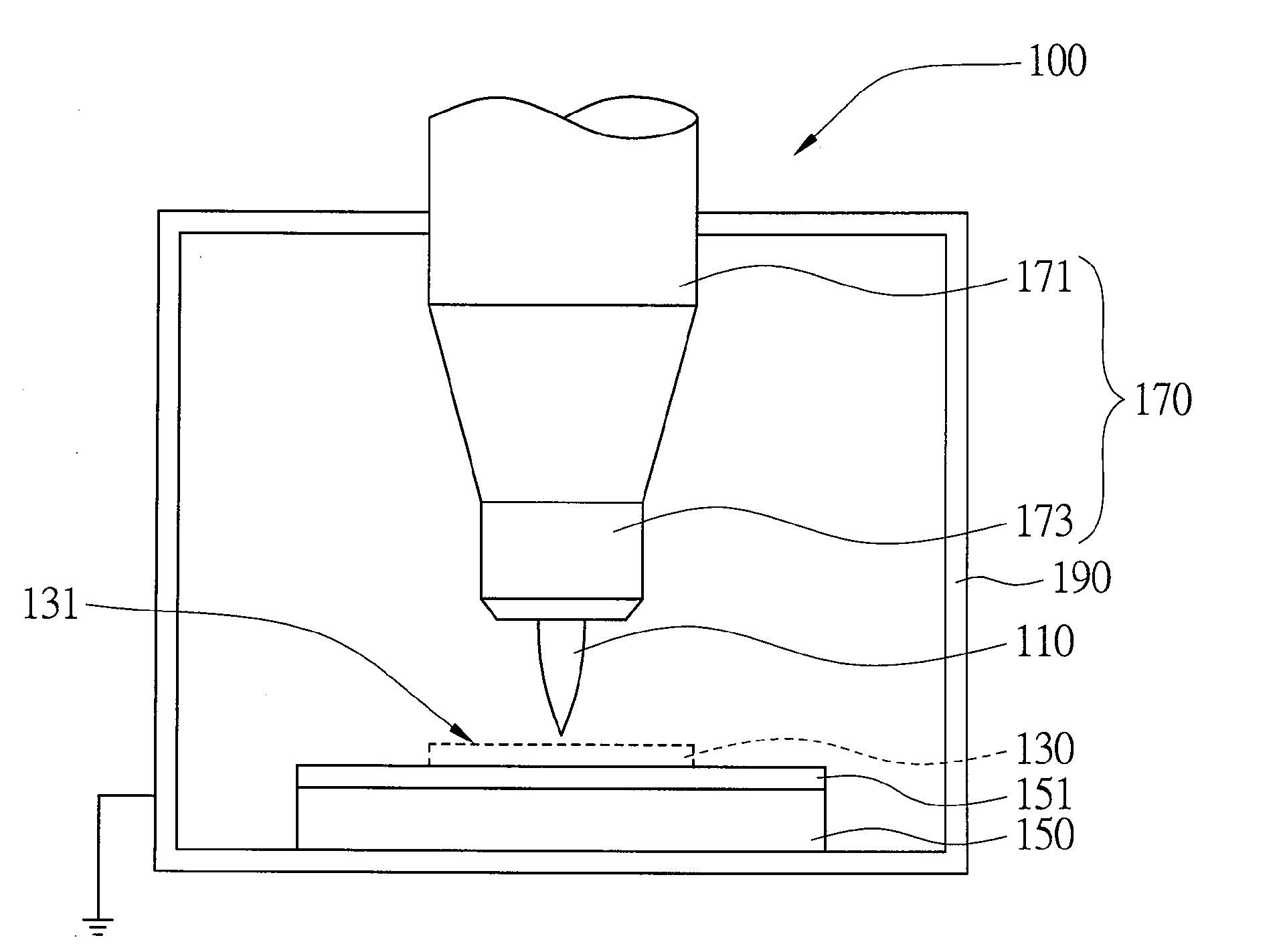
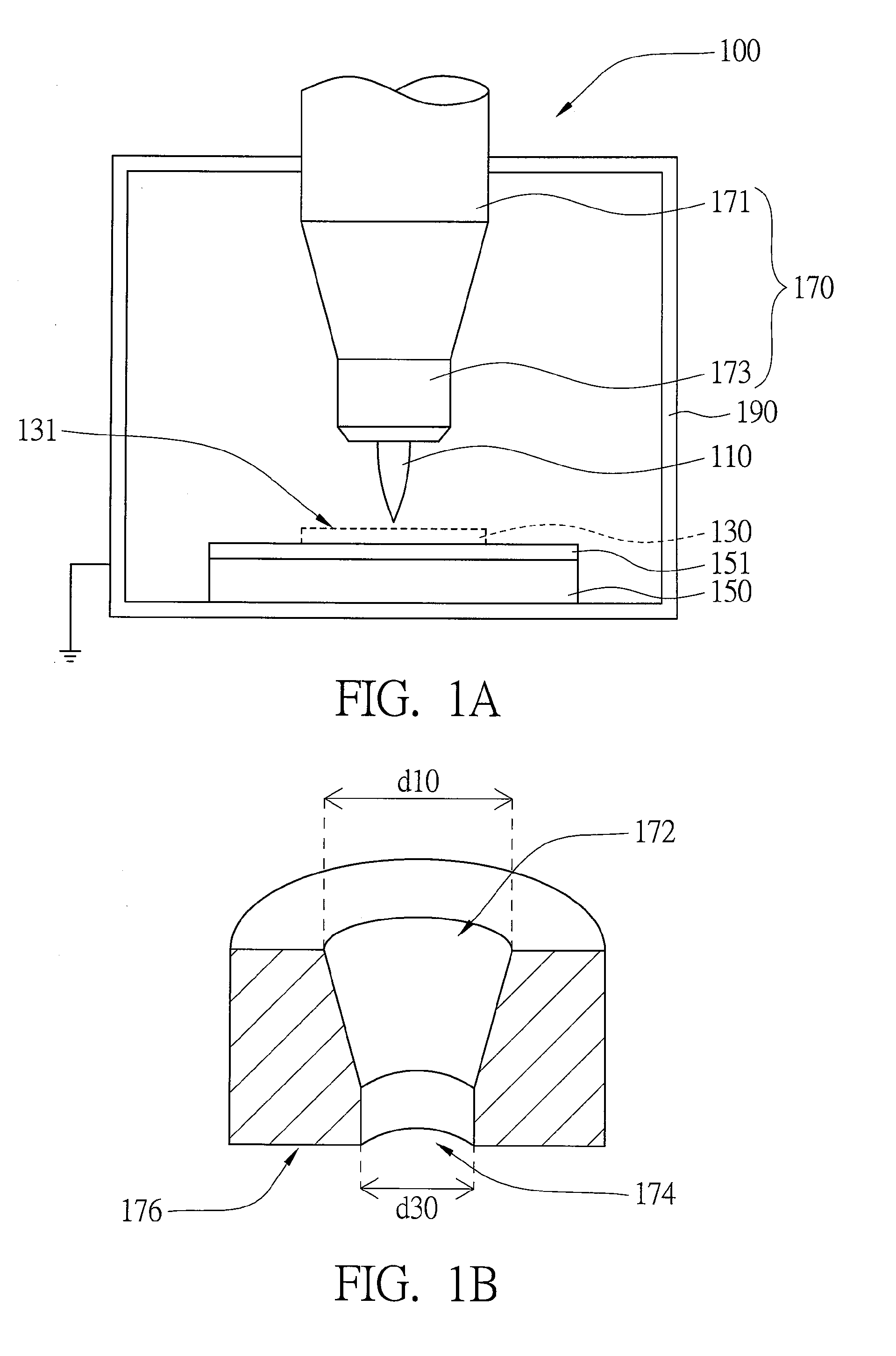
[0018]Referring to FIG. 1A and FIG. 1B, FIG. 1A shows a plasma device according to a first embodiment of the invention, and FIG. 1B is a partial cross-sectional view of a plasma nozzle in FIG. 1A. The plasma device 100 is for providing a plasma 110 to process a surface of a substrate 130. The plasma device 100 includes a base 150, a jet plasma gun 170 and a cavity 190. The jet plasma gun 170 includes a plasma producer 171 and a plasma nozzle 173. The substrate 130 is placed on a bearing surface of the base 150. The plasma producer 171 is for providing a plasma 110. The plasma nozzle 173 is disposed between the substrate 130 and plasma producer 171 and has a first opening 172 and a second opening 174. The first opening 172 faces plasma producer 171, and the second opening 174 faces the base 150. The cavity 190 is for receiving the base 150 and the plasma nozzle 173. The jet plasma gun 170 is fixed in cavity 190, and the bearing surface of the base 150 is electrically isolated from th...

second embodiment

[0023]The jet plasma gun of the second embodiment of the invention includes a barrier. As for other similarities between the first embodiment and the second embodiment, the same designations are used and are not repeated here.

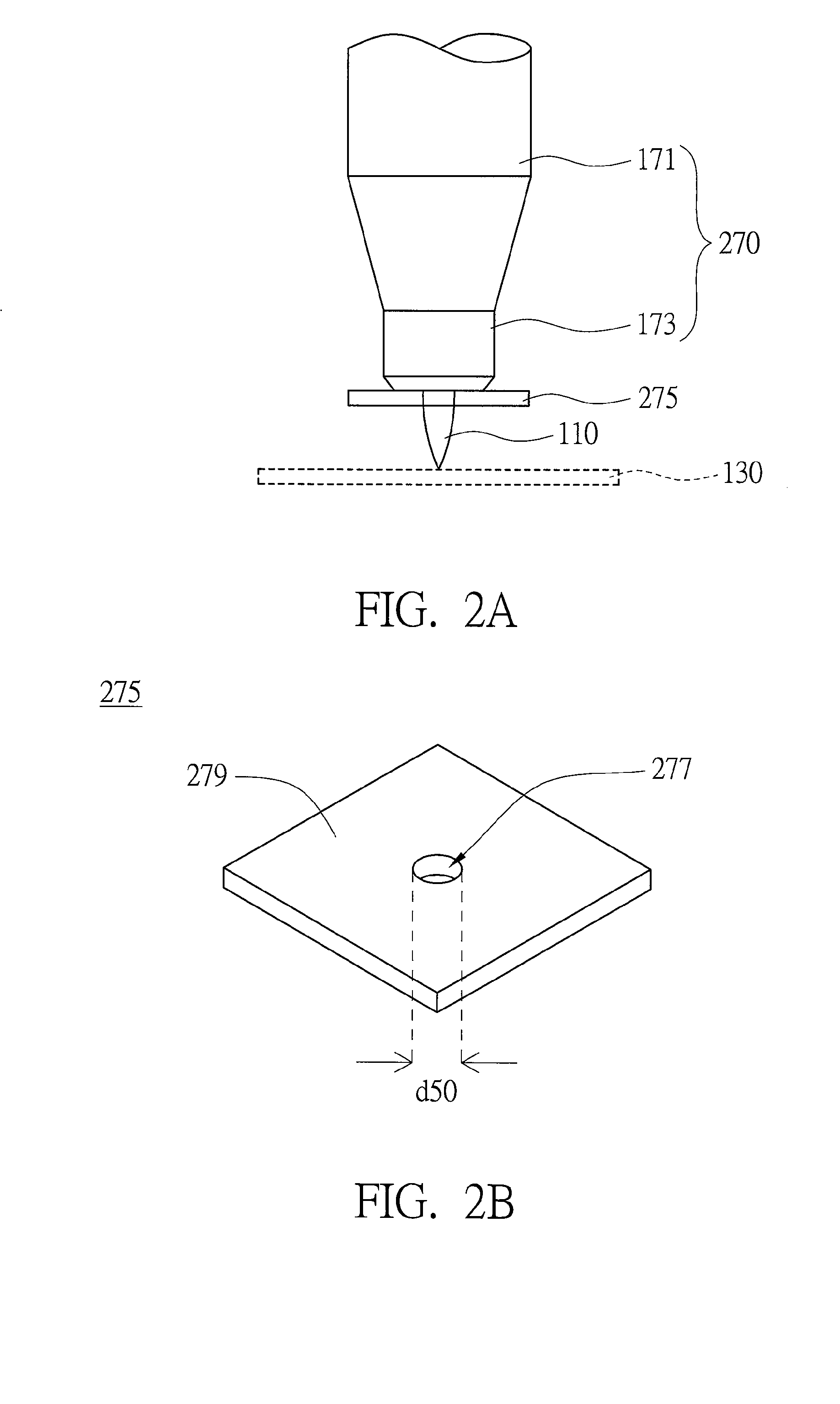
[0024]Referring to FIGS. 2A and 2B, FIG. 2A shows a jet plasma gun and a substrate according to a second embodiment of the invention, and FIG. 2B is a perspective view of a barrier of the jet plasma gun in FIG. 2A. The jet plasma gun 270 includes a plasma producer 171, a plasma nozzle 173 and a barrier 275. The barrier 275 being an insulator is disposed between plasma nozzle 173 and the substrate 130 and has a through hole 277 corresponding to the second opening 174 (illustrated in FIG. 1B. The plasma 110 passes through the plasma nozzle 173 and the through hole 277 to reach the substrate 130.

[0025]As indicated in FIGS. 1B and 2B, the barrier 275 is coupled to the plasma nozzle 173. The second opening 174 of the plasma nozzle 173 is disposed on a surface 176 of...


PUM

PropertyMeasurementUnit
Diameteraaaaaaaaaa
Areaaaaaaaaaaa
Distanceaaaaaaaaaa

Abstract

A jet plasma gun and a plasma device using the same are provided. The jet plasma gun is for jetting plasma to process a surface of a substrate. The jet plasma gun includes a plasma producer, a plasma nozzle and a barrier. The plasma producer is for providing plasma. The plasma nozzle disposed between the substrate and plasma producer has a first opening and a second opening. The first opening faces plasma producer, and the second opening faces the substrate. The barrier being an insulator is disposed between the plasma nozzle and the substrate and has a through hole corresponding to the second opening. The plasma passes through the plasma nozzle and the through hole to reach the substrate.

Description

[0001]This application claims the benefit of Taiwan application Serial No. 96150036, filed Dec. 25, 2007, the subject matter of which is incorporated herein by reference.BACKGROUND OF THE INVENTION[0002]1. Field of the Invention[0003]The invention relates in general to a plasma gun and a plasma device using the same, and more particularly to a jet plasma gun having a plasma nozzle and a plasma device using the same.[0004]2. Description of the Related Art[0005]As the semiconductor industry is experiencing rapid growth, various methods and devices for manufacturing process are provided and used. The plasma can be used for surface cleaning, surface etching, trench etching, thin-film deposition and surface component change on the surface of a substrate. Examples of the plasma device include the plasma cleaning device, plasma enhance chemical vapor deposition (PECVD) device, plasma enhance reactive ion etching (PERIE) device, micro-wave plasma oxidation device, micro-wave plasma nitridat...

Claims


Application Information

Patent Timeline
IPC IPC(8): C23F1/02C23C16/44C23C14/34
CPCH05H2001/3457H05H1/34H05H1/3457
Inventor CHANG, CHIA-CHIANGTSAI, CHEN-DERHSU, WEN-TUNGCHEN, CHIH-WEIWU, CHIN-JYI
Owner IND TECH RES INST
Learn More