Preserving apparatus for welded joint portion and preserving method therefor

a preservation apparatus and welded joint technology, applied in the direction of soldering apparatus, manufacturing tools,auxillary welding devices, etc., can solve the problems of difficult to ensure welding quality, the possibility of fine scc already existing on the inner surface of the welded joint portion of the pressure vessel, etc., and achieve the effect of sufficient welding quality

a preservation apparatus and welded joint technology, applied in the direction of soldering apparatus, manufacturing tools,auxillary welding devices, etc., can solve the problems of difficult to ensure welding quality, the possibility of fine scc already existing on the inner surface of the welded joint portion of the pressure vessel, etc., and achieve the effect of sufficient welding quality

US20090166338A1Inactive Publication Date: 2009-07-02IHI CORP

Image

  • Preserving apparatus for welded joint portion and preserving method therefor
  • Preserving apparatus for welded joint portion and preserving method therefor
  • Preserving apparatus for welded joint portion and preserving method therefor

Examples


Embodiment Construction

[0033]The preferred embodiments of the present invention will be described below in greater detail with reference to the appended drawings.

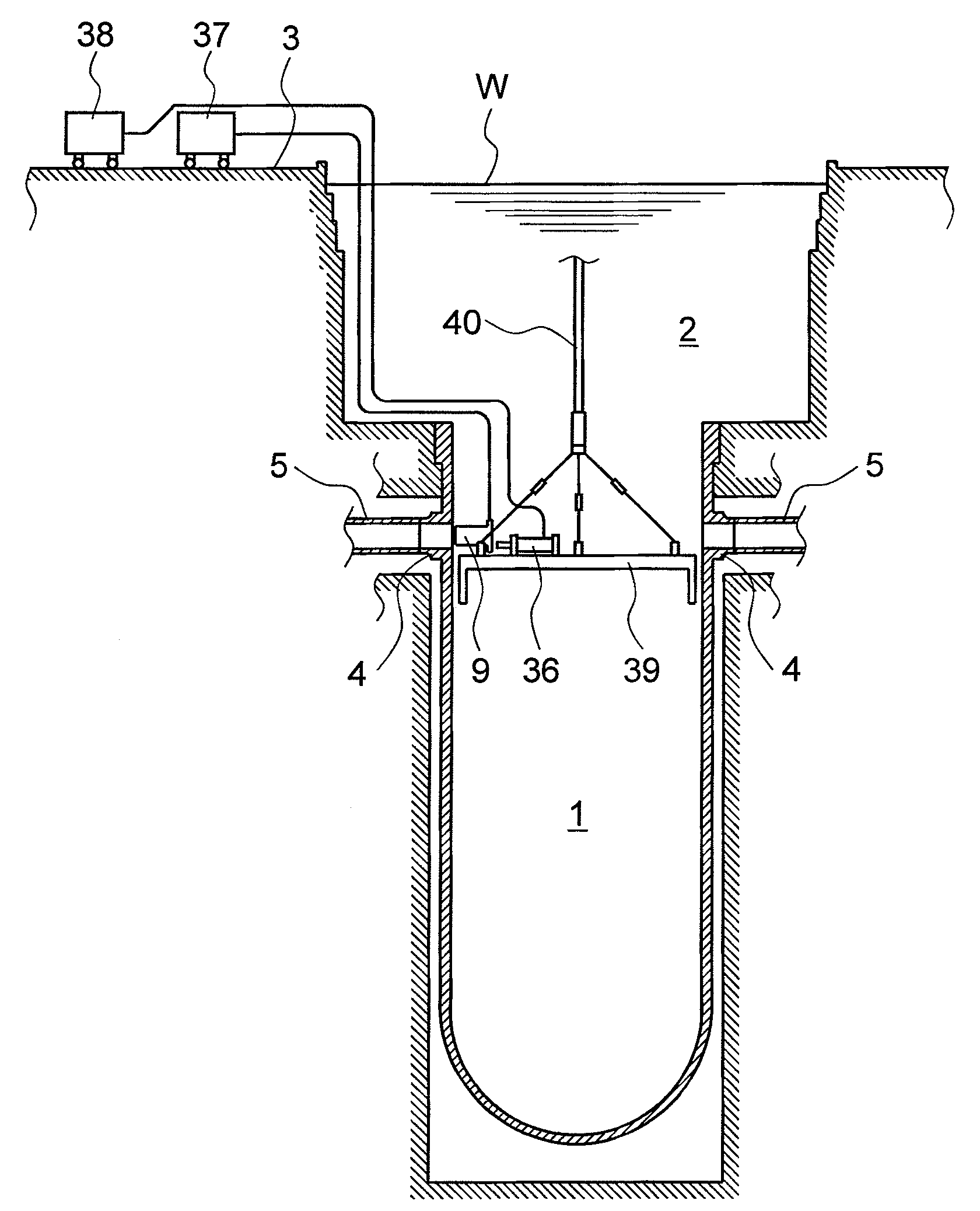
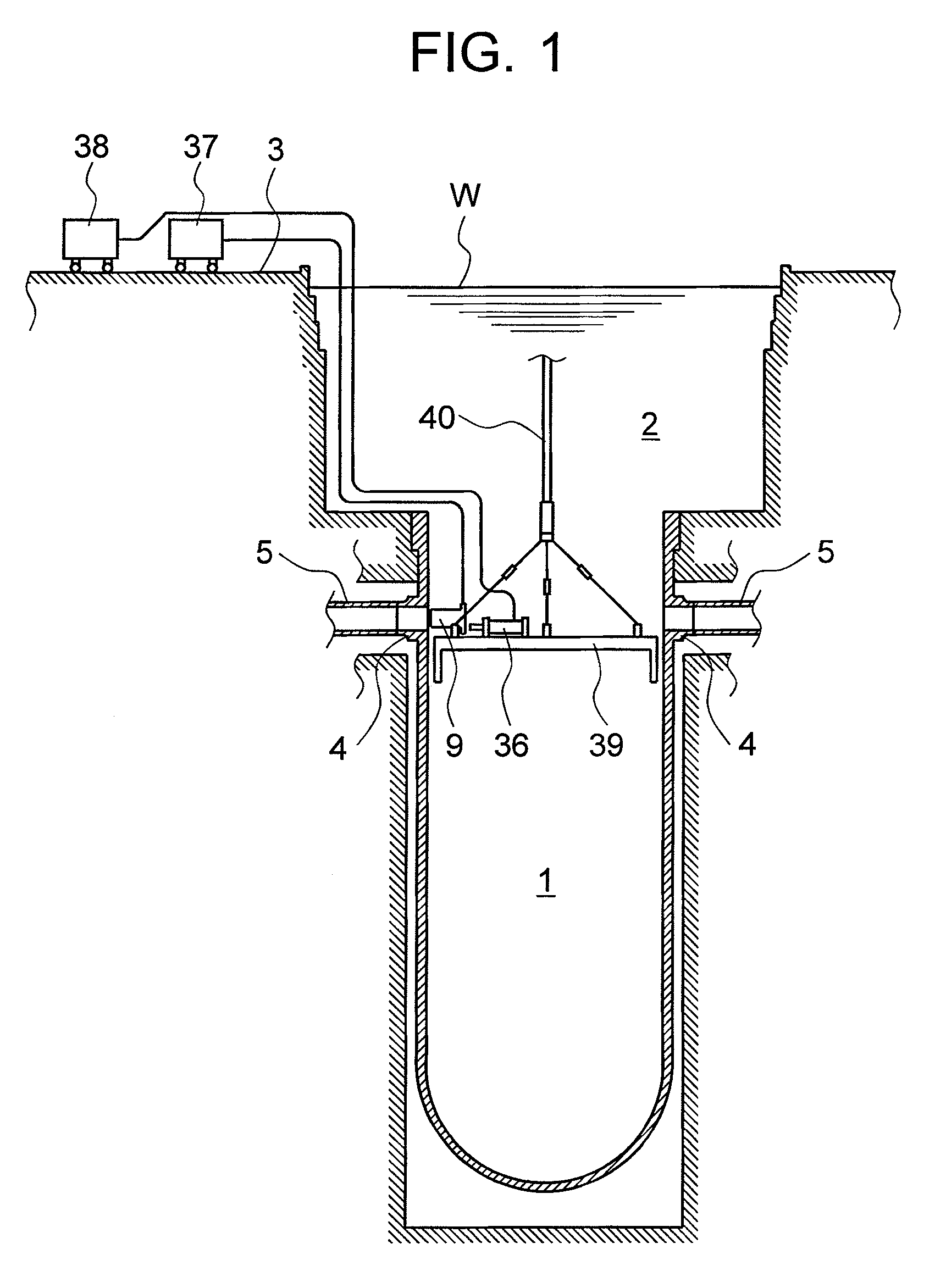
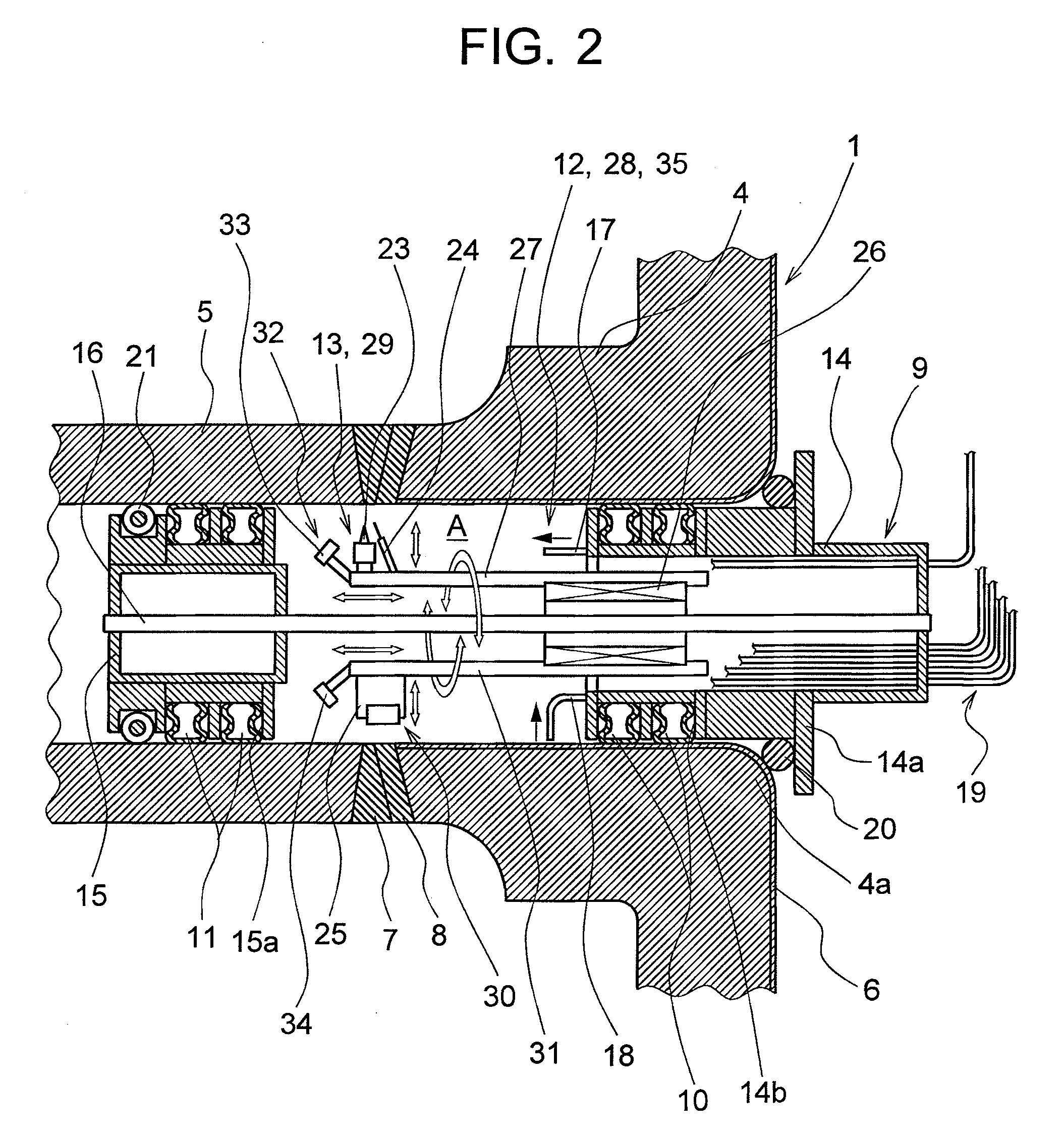
[0034]FIG. 1 is a schematic view of a nuclear reactor pressure vessel employing the preserving apparatus of an embodiment of the present invention. FIG. 2 is a cross-sectional view of a pressure vessel that illustrates a state prior to deposit welding. FIG. 3 is a cross-sectional view of a pressure vessel that illustrates a state after the deposit welding.

[0035]In FIG. 1, the reference numeral 1 stands for a pressure vessel, 2 stands for a nuclear reactor well, and 3 stands for an operation floor. The vessel 1 is a pressure vessel of a pressurized water reactor.

[0036]As shown in FIG. 2, a nozzle 4 that links the inside of the pressure vessel 1 with the outside is provided in the body portion of the pressure vessel 1. A pipe 5 such as a supply pipe for supplying cooling water into the pressure vessel 1 or an introducing pipe for introducing high-t...


PUM

PropertyMeasurementUnit
temperatureaaaaaaaaaa
areaaaaaaaaaaa
residual tensile stressesaaaaaaaaaa

Abstract

A preserving apparatus for preserving welded joint portions 7, 8 by deposit welding on the inner surface of the welded joint portions 7, 8, in which a nozzle 4 and a pipe 5 supported under water are joined, the apparatus having: a seal member 9 that is disposed in front and behind the welded joint portions 7, 8 to be deposit welded within the nozzle 4 and pipe 5, and serves to demarcate and form a closed operation area A within the nozzle 4 and pipe 5; water drainage means 12 for draining the inside of the operation area A demarcated and formed by the seal member 9 and obtaining a gas atmosphere therein; and welding means 13 for deposit welding on the inner surface of the welded joint portions 7, 8 within the operation area A in which the gas atmosphere has been created.

Description

CROSS REFERENCE TO RELATED APPLICATIONS[0001]This application is entitled to the benefit of and incorporated by reference essential subject matter disclosed in International Patent Application No. PCT / JP2006 / 307661 filed on Apr. 11, 2006.TECHNICAL FIELD[0002]The present invention relates to an apparatus for deposit welding on the inner surface of a welded joint portion, in which a nozzle and a pipe supported under water are joined, and preserving the welded joint portion and to a method therefor.BACKGROUND ART[0003]In the field of pressure vessels of nuclear reactors such as a BWR (Boiling Water Reactor) or a PWR (Pressurized Water Reactor), there is concern about residual tensile stresses remaining on the inner surface of welded joint portions in which a nozzle and a pipe provided in the pressure vessel are joined together and the occurrence of SCC (Stress Corrosion Cracking).[0004]In the pressure vessels of nuclear reactors, stress improvement by which tensile stresses remaining o...

Claims


Application Information

Patent Timeline
02 Jul 2009
Publication
US20090166338A1
IPC
B23K9/04
CPC
B23K9/0061; B23K9/0284; B23K9/32; B23K9/326; B23K37/0276; F16L13/02; F16L55/134; F16L55/18
Inventors
SATO, SEIICHI