Switching power converter with controlled startup mechanism

a startup mechanism and power converter technology, applied in the direction of electric variable regulation, process and machine control, instruments, etc., can solve the problems of affecting the operation of the converter

Active Publication Date: 2009-07-02
ANALOG DEVICES INC
View PDF6 Cites 24 Cited by
  • Summary
  • Abstract
  • Description
  • Claims
  • Application Information

AI Technical Summary

Benefits of technology

[0009]The converter also includes a capacitor connected to the output node and arranged to provide a current Ic to the feedback network which varies with dVout/dt. The feedback network is

Problems solved by technology

However, a converter arranged as shown can encounter a problem during the “startup” phase of its operation.
This causes the aver

Method used


Image

  • Switching power converter with controlled startup mechanism
  • Switching power converter with controlled startup mechanism
  • Switching power converter with controlled startup mechanism

Examples


Embodiment Construction

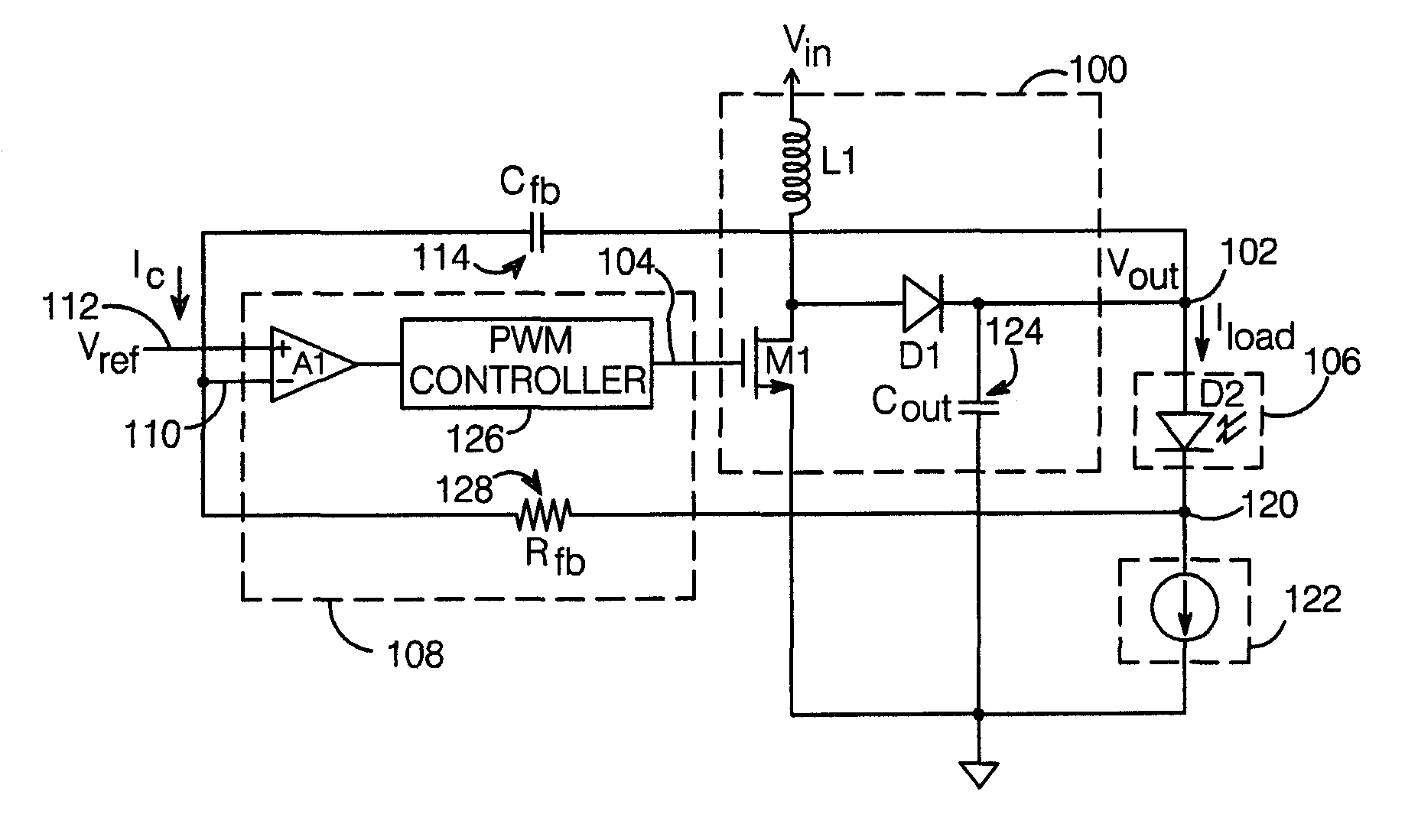
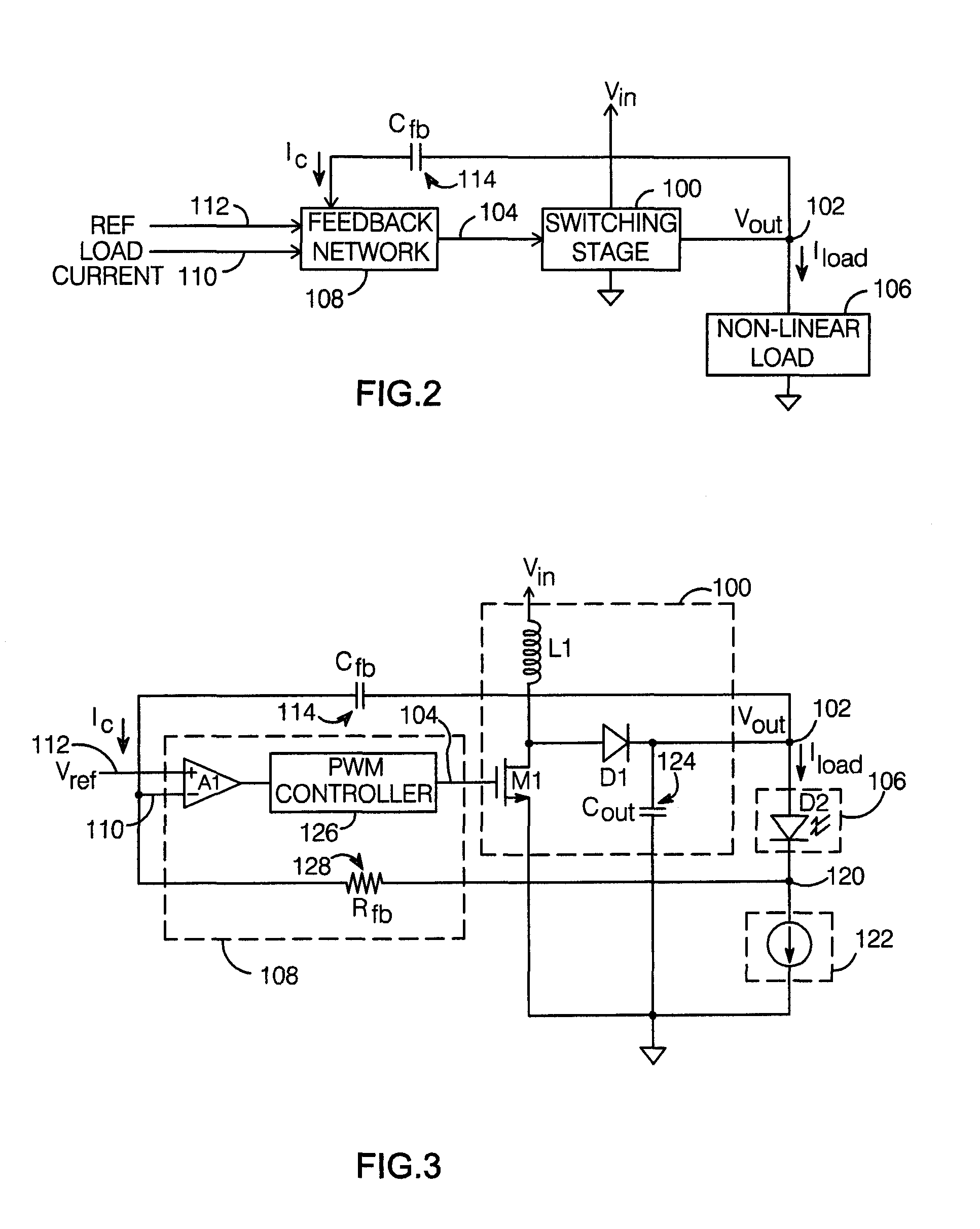
[0017]The principles of a switching power converter with a controlled startup mechanism per the present invention are illustrated in FIG. 2. The converter includes a switching stage 100 which would include the inductor and switching elements found in a switching converter; switching stage 100 provides the converter's output voltage Vout at an output node 102 in response to a switching control signal 104. Output node 102 is adapted for connection to a non-linear load 106. As used herein, a non-linear load is any load for which the current conducted by the load (Iload) does not vary linearly with the voltage applied across it. For example, one application for the present converter is the driving of one or more series-connected diodes such as light-emitting diodes (LEDs), in which the converter regulates the diode's cathode voltage so as to cause a desired current to flow in the diode. The converter is particularly useful when Vout must be relatively large, as might be needed when the ...


PUM


Abstract

A switching power converter with a controlled startup mechanism includes a switching stage which provides a voltage Vout at an output node in response to a switching control signal, with the output node adapted for connection to a non-linear load. A feedback network compares a signal which varies with the current conducted by the load (Iload) with a reference signal, and provides the switching control signal so as to maintain Iload at a desired value. A capacitor connected to the output node provides a current Ic to the feedback network which varies with dVout/dt. The feedback network is arranged to limit dVout/dt in response to current Ic when Iload is substantially zero. In this way, large inrush currents or damage that might otherwise occur during startup are avoided.

Description

BACKGROUND OF THE INVENTION[0001]1. Field of the Invention[0002]This invention relates generally to switching power converters, and more particularly, to a switching converter with a startup mechanism which is useful when the load being driven is non-linear.[0003]2. Description of the Related Art[0004]Switching power converters can be configured using a number of different topologies, can be controlled with a wide variety of control methods, and can be used to drive different types of loads. One possible arrangement is shown in FIG. 1. In this example, a boost converter topology is employed, in which an inductor 10 is connected between an input voltage Vin and a switching element—here, a transistor 12; a diode 14 is connected to the junction of the inductor and transistor, and the converter's output voltage Vout appears on the cathode side of diode 14. Vout drives a load 16—here, a diode—connected between Vout and a node 20, and a resistor 22 having a resistance R1 is connected betw...

Claims


Application Information

Patent Timeline
IPC IPC(8): H05B41/36G05F1/10
CPCH02M1/36H05B33/0851H05B33/0815H02M3/156Y10S323/908Y10S323/901H05B45/3725H05B45/38H05B45/14
Inventor BROKAW, A. PAULROESSIG, TREY
Owner ANALOG DEVICES INC
Why Eureka
Try Eureka