
Methods and apparatus for transferring a material onto a substrate using a resonant infrared pulsed laser

a pulsed laser and infrared technology, applied in the field of pulse laser deposition, can solve the problems of low repetition rate of available lasers, lack of commercially available high-power lasers, chemical modification of polymers,

Inactive Publication Date: 2009-07-02
VANDERBILT UNIV
View PDF24 Cites 34 Cited by
  • Summary
  • Abstract
  • Description
  • Claims
  • Application Information

AI Technical Summary

Problems solved by technology

These include the slow repetition rate of the available lasers, and the lack of commercially available high power lasers.
Therefore, even in some of the most successful cases of ultraviolet PLD, the intense interaction between the target material and laser leads to chemical modification of the polymer.
Finding a suitable solvent system that is also non-photochemically active is a significant challenge and limits the usefulness of the technique.
There are examples where electronic excitation of the solvent / polymer system has been observed to produce undesirable photochemical modification of the polymer, such as reduction in the average weight average molecular weight.
An additional disadvantage of the matrix-assisted pulsed laser evaporation is that the deposition rate is about an order of magnitude lower than conventional PLD, which can render matrix-assisted pulsed laser evaporation ineffective for applications that require thick, i.e., greater than about 1 μm, coatings.
While UVPLD has been used to deposit much thinner (on the order of a few hundred angstroms) coatings on drug particles, the deposition process introduces significant and undesirable chemical modification in the coating material as a consequence of the ultraviolet excitation.
They are a promising candidate for integration into mesoscale devices, including micro-electro-mechanical systems (hereinafter “MEMS”), however, bottom-up manipulation of these and other thermoset polymers is difficult on length scales below a few microns.
Laser processing of polyimides has been largely limited to ablation.
Therefore, a heretofore unaddressed need still exists in the art to address the aforementioned deficiencies and inadequacies.

Method used


Image

  • Methods and apparatus for transferring a material onto a substrate using a resonant infrared pulsed laser
  • Methods and apparatus for transferring a material onto a substrate using a resonant infrared pulsed laser
  • Methods and apparatus for transferring a material onto a substrate using a resonant infrared pulsed laser

Examples


Embodiment Construction

[0035]The present invention is more particularly described in the following examples that are intended as illustrative only since numerous modifications and variations therein will be apparent to those skilled in the art. Various embodiments of the invention are now described in detail. Referring to the drawings, like numbers indicate like parts throughout the views. As used in the description herein and throughout the claims that follow, the meaning of “a,”“an,” and “the” includes plural reference unless the context clearly dictates otherwise. Also, as used in the description herein and throughout the claims that follow, the meaning of “in” includes “in” and “on” unless the context clearly dictates otherwise.

[0036]The description will be made as to the embodiments of the present invention in conjunction with the accompanying drawings 1-10. In accordance with the purposes of this invention, as embodied and broadly described herein, this invention, in one aspect, relates to a method ...


PUM

PropertyMeasurementUnit
molecular sizeaaaaaaaaaa
pulse repetition frequencyaaaaaaaaaa
repetition frequencyaaaaaaaaaa

Abstract

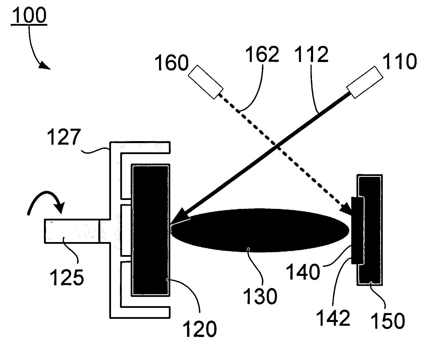
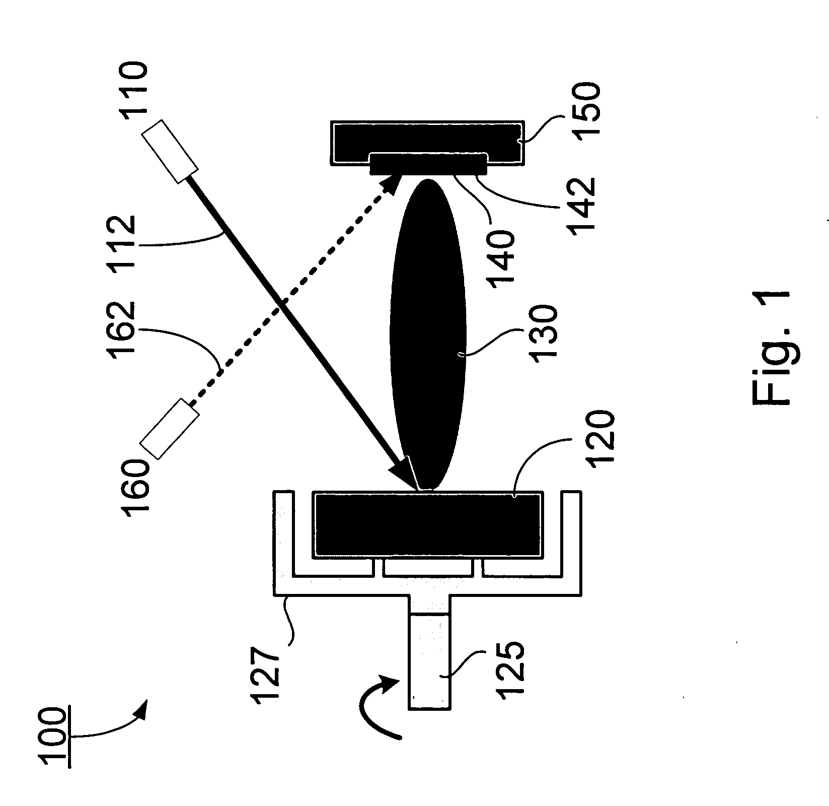
A method for transferring a material onto a substrate. In one embodiment, the method includes the steps of directing a coherent light of a wavelength resonant with a vibrational mode of the material at the material to vaporize the material, depositing the vaporized material on the substrate in a form that is essentially same chemically as the material, and selectively heating the deposited material at one or more positions of the substrate to form a film thereon.

Description

CROSS-REFERENCE TO RELATED PATENT APPLICATION[0001]This application is a continuation-in-part of U.S. patent application Ser. No. 10 / 059,978, filed Jan. 29, 2002, entitled “Deposition of Thin Films Using an Infrared Laser,” by Daniel Bubb, James Horwitz, John Callahan, Richard Haglund, Jr. and Michael Papantonakis, the disclosure of which is hereby incorporated herein by reference in its entirety. This application also claims the benefit, pursuant to 35 U.S.C. §119(e), of U.S. provisional patent application Ser. No. 60 / 714,819, filed Sep. 7, 2005, entitled “A Resonant Infrared Pulsed Laser System for Transferring a Material Onto a Substrate and Applications of Same,” by Richard F. Haglund, Jr., Nicole L. Dygert, and Kenneth E. Schriver, which is incorporated herein by reference in its entirety.[0002]Some references, which may include patents, patent applications and various publications, are cited and discussed in the description of this invention. The citation and / or discussion of ...

Claims


Application Information

Patent Timeline
Patent Type & Authority Applications(United States)
IPC IPC(8): B32B5/16B05D3/00B05D3/06C23C16/56B32B27/00
CPCC23C14/12Y10T428/254C23C14/28Y10T428/31855Y10T428/31938Y10T428/3154Y10T428/31721B32B5/16
Inventor HAGLUND, JR., RICHARD F.DYGERT, NICOLE L.SCHRIVER, KENNETH E.
Owner VANDERBILT UNIV
Learn More