
Mri-safe high impedance lead systems

a high impedance, lead technology, applied in the direction of internal electrodes, transvascular endocardial electrodes, therapy, etc., can solve the problems of local tissue damage around the electrodes of these leads, local tissue damage, local tissue damage, etc., and achieve the effect of high impedan

Active Publication Date: 2009-07-02
BOSTON SCI NEUROMODULATION CORP
View PDF99 Cites 137 Cited by
  • Summary
  • Abstract
  • Description
  • Claims
  • Application Information

AI Technical Summary

Benefits of technology

The present invention provides therapeutic lead systems that can be used in interventional devices and implantable medical devices. These lead systems have high impedance properties that prevent RF current from heating tissue and causing damage. The lead systems can include a plurality of high impedance sections or segments that act as RF traps to inhibit RF transmission. The lead systems can also have a high impedance at a high range of radiofrequencies and a low impedance at a low range of frequencies. The lead systems can be used in MRI compatible devices and can include a decoupling circuit to provide high impedance at high radiofrequencies and low impedance at low radiofrequencies. The lead systems can also include a high impedance band gap surface or a plurality of inductors and capacitors to reduce RF transmission. Overall, the lead systems have improved safety and reliability in interventional procedures and can provide better therapeutic outcomes.

Problems solved by technology

When patients implanted with deep brain stimulation (DBS) or cardiac pacing (CP) lead systems are exposed to external Radio Frequency (RF) fields, local tissue damage around the electrodes of these leads can occur as has been reported by various researchers.
Local tissue damage during RF diathermy procedures in patients with implanted deep brain stimulator lead systems has also been reported.
Local tissue damage can be caused by RF deposition in the tissue that is in close proximity to the linear conductors or electrodes of the lead system, when patients with implanted leads or interventional devices are placed in an external RF field.
Where the current emerges from the distal tip of the device (or adjacent to the electrode in the case of an implantable lead), it can be concentrated and can cause heating and subsequent tissue damage.

Method used


Image

  • Mri-safe high impedance lead systems
  • Mri-safe high impedance lead systems
  • Mri-safe high impedance lead systems

Examples


Embodiment Construction

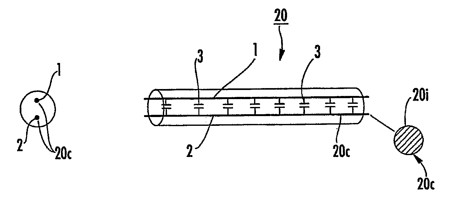
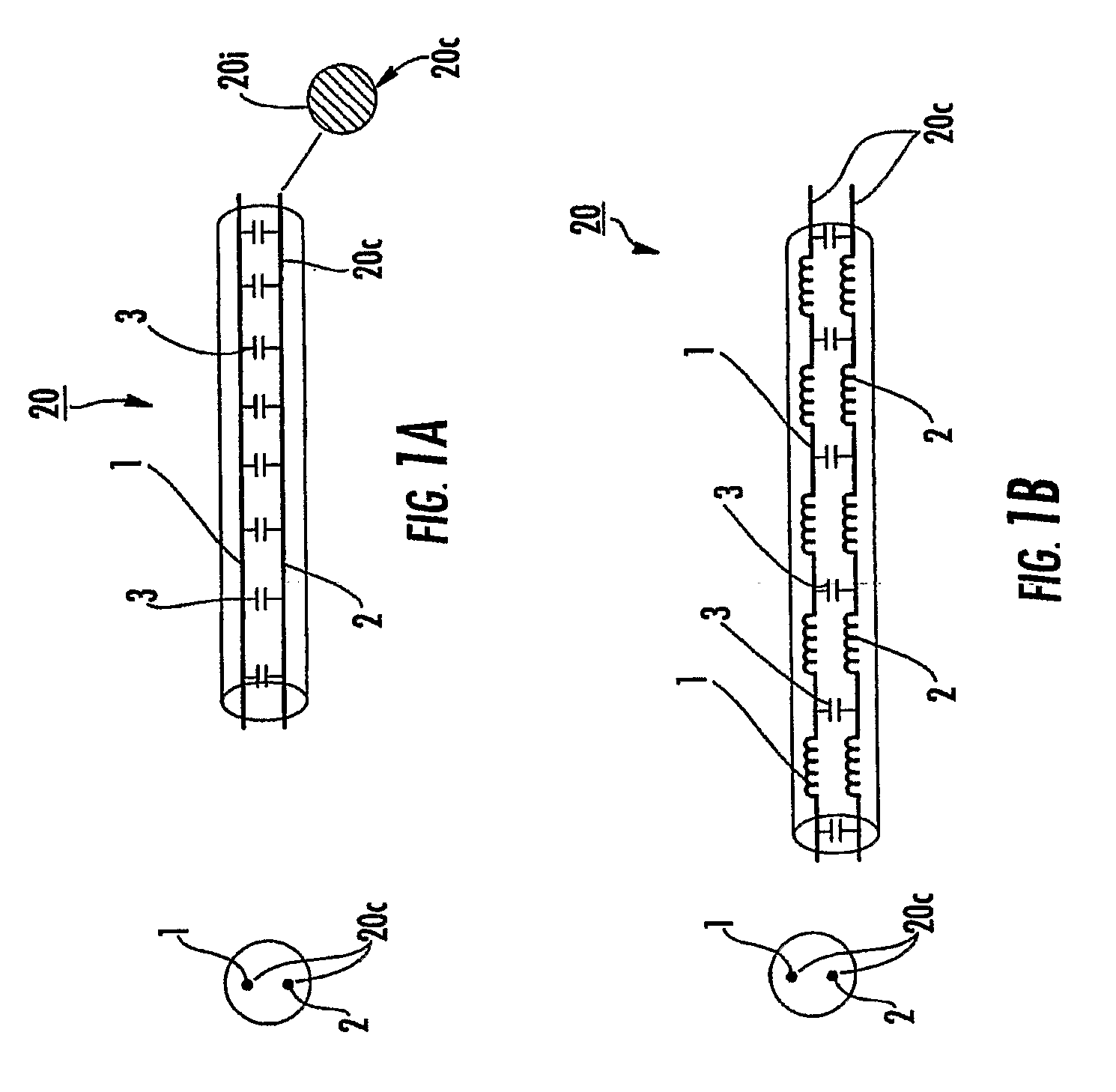
[0007]Some embodiments of the present invention provide therapeutic lead systems that can exhibit high impedance during exposure to RF (high frequencies).

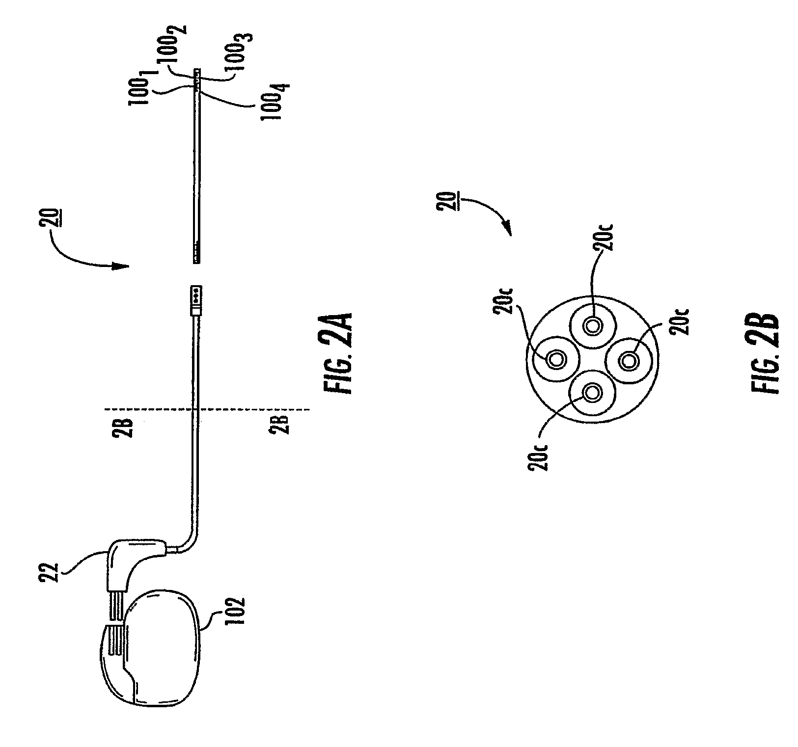
[0008]The lead systems can be used with interventional devices and may be acutely placed in vivo or chronically implantable and can include one or more stimulating, ablating and / or recording electrode. The lead systems may be particularly suitable for implantable lead systems for IPGs (implantable pulse generators), cardiac defibrillators, cardiac pacing (CP), neurostimulation (peripheral, deep brain, or spinal), EP catheters, guidewires, and the like, for leads used in heat-sensitive regions in the body.

[0009]The lead systems may be implantable, MRI compatible multi-purpose lead systems with at least one stimulating / pacing electrode and may optionally be configured to provide an internal MRI receive antenna.

[0010]In some embodiments, the lead systems can include a plurality of high impedance sections or segments spaced along the l...


PUM


Abstract

Some embodiments are directed to MRI / RF compatible medical interventional devices. A plurality of spaced apart high impedance circuit segments are configured to have a high impedance at a high range of radiofrequencies and a low impedance at a low range of frequencies The high impedance circuit segments may comprise co-wound coiled inductors and can reduce, block or inhibit RJ-transmission along the lead system (20) during exposure to RF associated with a high-Held magnet MRI systems, while permuting passage of low frequency physiologic signals, treatments and / or stimuli The devices can include at least one electrode

Description

RELATED APPLICATION[0001]This application claims the benefit of priority of U.S. Provisional Application Ser. No. 60 / 729,020, filed Oct. 21, 2005, the contents of which are hereby incorporated by reference as if recited in full herein.FIELD OF THE INVENTION[0002]The present invention relates to interventional medical leads and may be particularly suitable for MRI compatible implantable devices such as cardiac pacing devices and Deep Brain Stimulation (“DBS”) and / or sympathetic nerve chain stimulation leads.BACKGROUND OF THE INVENTION[0003]When patients implanted with deep brain stimulation (DBS) or cardiac pacing (CP) lead systems are exposed to external Radio Frequency (RF) fields, local tissue damage around the electrodes of these leads can occur as has been reported by various researchers. See, e.g., Baker et al., Neurostimulation systems: assessment of magnetic field interactions associated with 1.5- and 3-Tesla MR systems, J Magn Reson Imaging 2005; 21(1):72-77; Bhidayasiri et ...

Claims


Application Information

Patent Timeline
Patent Type & Authority Applications(United States)
IPC IPC(8): A61N1/05
CPCA61N1/056A61N1/06A61N2001/086A61N1/086
Inventor ATALAR, ERGINALLEN, JUSTINBOTTOMLEY, PAULELDELSTEIN, WILLIAMKARMARKAR, PARAG V.
Owner BOSTON SCI NEUROMODULATION CORP
Learn More