
Computational scheme for MEMS inertial navigation systemes

a navigation system and inertial sensor technology, applied in wave based measurement systems, navigation instruments, instruments, etc., can solve the problems of increasing inaccuracy, inability to provide high accuracy at long ranges, and increasing inaccuracy, so as to ensure stability, low cost, and low cost

Active Publication Date: 2009-07-02
ALPINE ELECTRONICS INC
View PDF1 Cites 13 Cited by
  • Summary
  • Abstract
  • Description
  • Claims
  • Application Information

AI Technical Summary

Benefits of technology

[0007]It is, therefore, an object of the present invention to provide a suite of computational methods with light computational burden yet with guaranteed stability for a low cost INS / GPS navigation system which utilizes low cost MEMS sensors in its IMU to track the platform three-dimensional position, three-dimensional-velocity, and three-dimensional orientation assuming the representative dynamics of commercial vehicles.
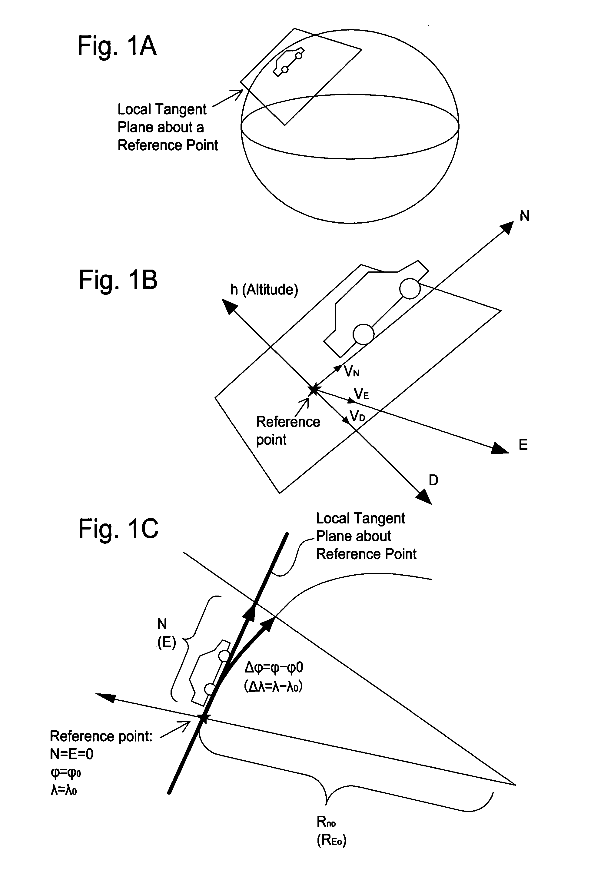
[0008]One aspect of the present invention is to consider that Earth is flat when tracking the platform three-dimensional position, i.e., a local tangent plane is used. This assumption is applicable to low-speed and low-altitude vehicles, e.g., ground vehicles and vessels. This will reduce cumbersome computation of the Earth North-South radius of curvature (RN) and East-West radius of curvature (RE) from the INS high-frequency computation.
[0011]Another aspect of the present invention is to focus on the platform dynamics with −90 (deg)<pitch<90 (deg) and −90 (deg)<roll<90 (deg), i.e., a platform without making vertical ascent / descent nor rolling over more than 90 degrees, which is natural to most of commercial vehicles including ground vehicles, vessels, and even commercial aircraft. These conditions (limited degrees of rotation) reduce the number of necessary parameters to track three-dimensional orientation.

Problems solved by technology

However, the INS cannot provide high accuracy at long ranges.
This is because inertial sensors are subject to errors that tend to accumulate over time, i.e., the longer the drive time, the greater the inaccuracy.
However, since the GPS relies on GPS satellites, it is susceptible to jamming, RF (radio frequency) interference and multipath problems.
Although the GPS provides accurate position and velocity over longer time periods, the GPS involves occasional large multipath errors and signal dropouts.
Inertial sensors used to be expensive and bulky, thus only used in precision application, e.g., aerospace and military navigation.
Because of the large amount of noise and bias, however, use of the conventional formula for a system with low-cost MEMS sensors is unnecessarily detailed and often results in numerical instability which often happens as soon as GPS signals are lost.
Also, assumptions of free orientation, free speed, and free altitude made in the conventional method result in unnecessary computation for most of commercial vehicles whose pitch and roll angles are restricted within −90 to +90 degrees with low speed and altitude.

Method used


Image

  • Computational scheme for MEMS inertial navigation systemes
  • Computational scheme for MEMS inertial navigation systemes
  • Computational scheme for MEMS inertial navigation systemes

Examples


Embodiment Construction

[0024]The present invention will be described in detail with reference to the accompanying drawings. The method and apparatus of the present invention takes advantages of the conditions featured in the platform dynamics and low-precision MEMS sensor performance. It should be noted that although a road vehicle is mainly used in the following description, the present invention can be advantageously implemented to other types of vehicles such as vessels, commercial aircrafts, etc.

[0025]To compute platform (vehicle) three-dimensional position, the conventional precision method tracks latitude φ, longitude λ, and altitude h by numerically integrate their time derivatives at a high frequency. The time derivatives of latitude φ is the functions of velocity vN, Earth North-South radius of curvature RN, longitude λ, and altitude h, while the time derivatives of longitude λ is the functions of velocity vE, Earth East-West radius of curvature RE, latitude φ, and altitude h. The time derivative...


PUM


Abstract

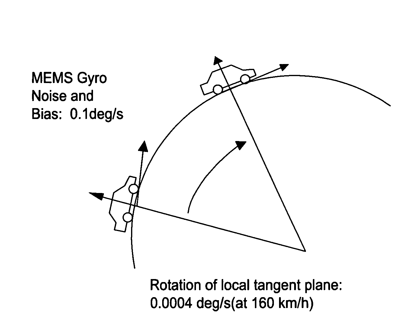
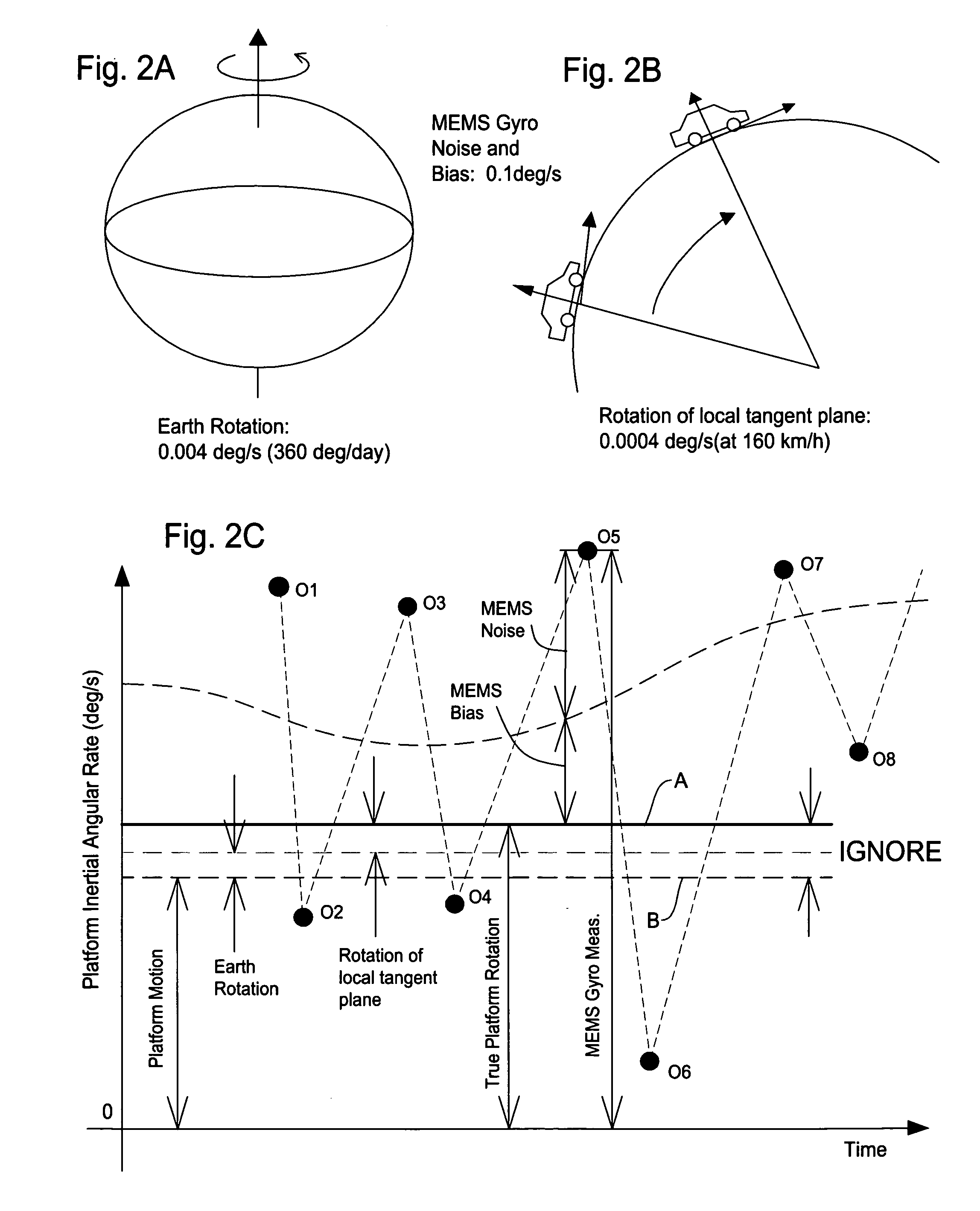
A computational scheme for an INS which utilizes micro-electro mechanical systems (MEMS) sensors is disclosed resolving issues of unnecessarily large computational burden and numerical instability which happen in using conventional methods using high-end inertial sensors. The first aspect to reduce computational burden in MEMS application is to omit computing Earth radii of curvatures that were used in a high-frequency application. The second aspect is to ignore the Earth rotation and the rotation of the local tangent plane with respect to Earth in the computation which are much smaller than noise and bias in the MEMS sensor output. The last aspect is to assume that the absolute amount of the platform pitch and roll angles is less than 90 degrees. This assumption results in only four parameters required to track in the direction cosine matrix describing the transformation from the local tangent plane to the platform where all the nine elements are tacked in the conventional method. According to the aspects noted above, the computational load will be one-fourth of the conventional method without degradation of accuracy.

Description

FIELD OF THE INVENTION[0001]This invention relates to a method involving a vehicle navigation system, and more particularly, to a computational scheme for the inertial navigation system (INS) which utilizes low-precision micro-electro mechanical systems (MEMS) sensors for simplifying the computational burden to compute the platform six degrees of freedom (DOF) motion.BACKGROUND OF THE INVENTION[0002]The INS is a widely used technology for guidance and navigation of a vehicle. The INS is composed of an inertial measurement unit (IMU) and a processor wherein an IMU houses accelerometers and gyroscopes which are inertial sensors detecting platform motion with respect to an inertial coordinate system. An important advantage of the INS is independence from external support, i.e., it is self-contained. However, the INS cannot provide high accuracy at long ranges. This is because inertial sensors are subject to errors that tend to accumulate over time, i.e., the longer the drive time, the ...

Claims


Application Information

Patent Timeline
IPC IPC(8): G01C21/26G01S5/00G06F17/16G06F17/10
CPCG01S19/49G01C21/16G01C21/188
Inventor HOSHIZAKI, TAKAYUKITASHIRO, ERIC
Owner ALPINE ELECTRONICS INC
Learn More