Device for accurately measuring amplifier's open-loop gain with digital stimuli

an amplifier and digital stimulus technology, applied in the direction of resistance/reactance/impedence, voltage-current phase angle, instruments, etc., can solve the problems of inaccurate measurement of inability to precisely predict open-loop gain, and inability to accurately measure open-loop gain of opamps. to achieve the effect of accurately measuring the open-loop gain of an opau

Active Publication Date: 2009-07-02
NAT CHIAO TUNG UNIV
View PDF2 Cites 11 Cited by
  • Summary
  • Abstract
  • Description
  • Claims
  • Application Information

AI Technical Summary

Benefits of technology

[0013]A first aspect of the present invention is to provide a device capable of receiving one or more digital input stimulus signals and accurately measuring the open-loop gain of an OPAUT. The device includes: a digital charge converter (DCC), composed of one or more sampling capacitors and a plurality of switches for receiving a plurality of control signals and a plurality of reference signals to output a charge signal; a charge integrator, comprising an OPAUT with a single-end output and at least one integrating capacitor for receiving the charge signal of the DCC and at least one of the reference signals and outputting an integration signal, the OPAUT including a positive input and a negative input, the integration signal being generated by amplifying a potential difference across the positive input and the negative input; an A/D converter, receiving the integration signal of the charge integrator

Problems solved by technology

Unfortunately the open-loop gains of the OPAMPs are very vulnerable to process variation.
Sometimes, even the SPICE (Simulation Program with Integrated Circuit Emphasis) simulation results could not precisely predict what the open-loop gains will be.
Traditionally, the open-loop gains are measured with an expensive network analyzer and a tedious testing setup.
Furthermore, the limited observation pins makes measuring the embedded OPAMPs' open-loop gains being troublesome and costly.
This method may not be applied to test the OPAUT in an SOC chip due to the limited driving capability of the OPAUT and limited observation nodes of the chip.
More than two poles in the transfer function of the OPAUT may lead to significant measurement errors.
This method does not require a costly netw

Method used


Image

  • Device for accurately measuring amplifier's open-loop gain with digital stimuli
  • Device for accurately measuring amplifier's open-loop gain with digital stimuli
  • Device for accurately measuring amplifier's open-loop gain with digital stimuli

Examples


first embodiment

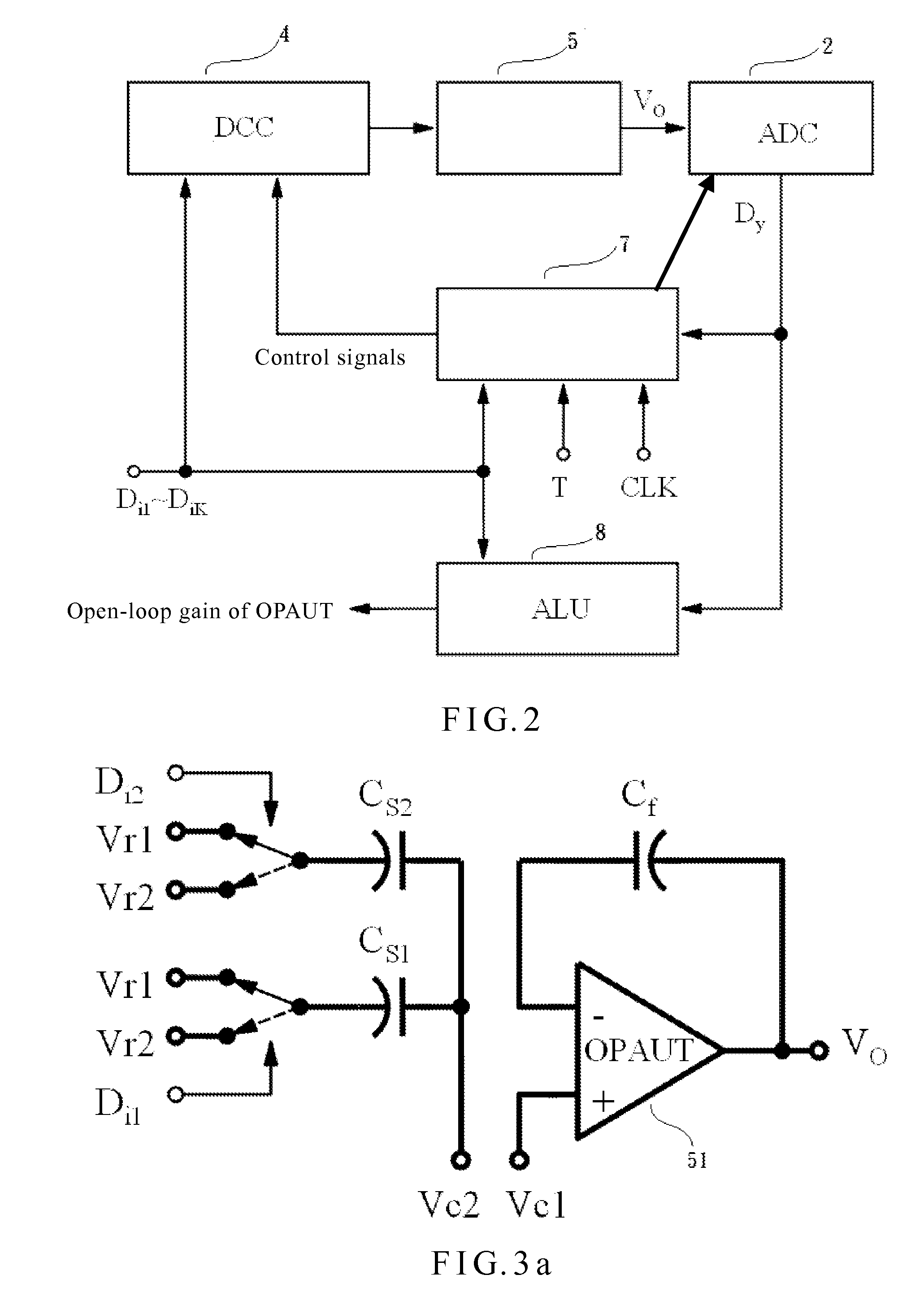
[0026]With reference to FIG. 2, a device capable of receiving one or more digital input stimulus signals and accurately measuring the open-loop gain of an OPAUT in accordance with the present invention is shown in a block diagram. As shown in FIG. 2, the device includes a digital charge converter (DCC) 4, a charge integrator 5, an A / D converter 2, a control logic circuit 7 and an arithmetic logic unit (ALU) 8. The digital charge converter (DCC) 4 is composed of one or more sampling capacitors and a plurality of switches controlled by a plurality of control signals and outputs a charge signal based on at least one of the digital input stimulus signals, a digital feedback signal and a plurality of reference signals. Each of the digital input stimulus signals is a Sigma-Delta modulated digital stimulus bit-stream which comprises two logic states, i.e., a first logic state and a second logic state. The charge integrator 5 includes an OPAUT 51 with a single-ended output and at least one ...

third embodiment

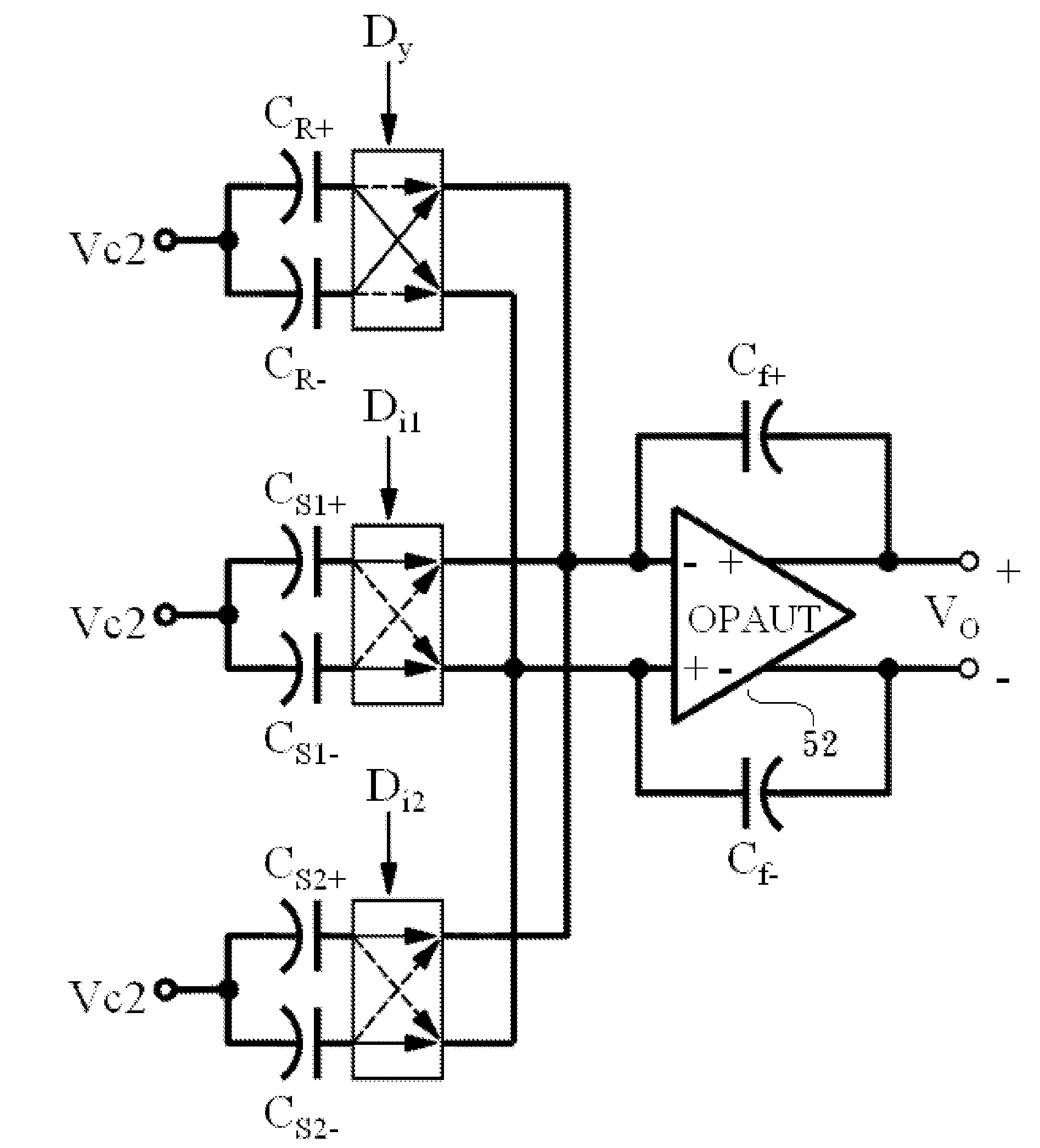
[0051]A fourth preferred embodiment of the present invention is described subsequently. In this embodiment, in addition to the components of the third embodiment, a device capable of receiving one or more digital stimulus signals and accurately measuring the open-loop gain of an OPAUT further includes at least one independently switching capacitor pair in the DCC 4′. The independently switching capacitor pair which is composed of a first independently switching capacitor (CR+) and a second independently switching capacitor (CR−) can independently switch the reference signals among the negative input and the positive input of the OPAUT 52 in accordance with the state of the digital feedback signal. If the OPAUT is in an ideal condition, and if the first logic state of the digital input stimulus signals is defined as +1, the second logic state of the digital input stimulus signals is defined as −1, the maximum state of the digital feedback state is defined as +1, the minimum logic sta...

fourth embodiment

[0056]With reference to FIG. 7a and FIG. 7b, FIG. 7a and FIG. 7b show the DCC 4′ and the charge integrator 5′ in the present invention operated in the first clock phase and the second clock phase respectively. The negative input of the OPAUT 52 is connected to the positive plate of the first integrating capacitor (Cf+). The positive input of the OPAUT 52 is connected to the positive plate of the second integrating capacitor (Cf−).The positive output of the OPAUT 52 is connected to the negative plate of the first integrating capacitor (Cf+). The negative output of the OPAUT 52 is connected to the negative plate of the second integrating capacitor (Cf−).

[0057]FIG. 7a shows that the device is operated in the first clock phase. The negative plates of the first sampling capacitors (Cs1+, Cs2+) of the sampling capacitor pairs and the first independently switching capacitor (CR+) of the independently switching capacitor pair are connected to the third reference signal (Vr1). The negative p...


PUM


Abstract

A device capable of receiving one or more digital stimulus signals and accurately measuring an open-loop gain of an amplifier comprises: a digital charge converter (DCC), a charge integrator, an A/D converter, a control logic circuit and an arithmetic logic unit (ALU). The DCC and the charge integrator are composed of a plurality of switches, one or more sampling capacitor, at least one integrating capacitor and an operational amplifier under test (OPAUT) with a single-ended output or differential-ended outputs. The DCC, the charge integrator, and the A/D converter are controlled by control signals generated by the logic control circuit and can be reconfigured as a first-order Sigma-Delta modulator capable of receiving at least one of the digital input stimulus signals. The ALU calculates the open-loop gain of the OPAUT with single-ended output or differential-ended outputs according to the digital stimulus signals and the digital output of the first-order Sigma-Delta modulator.

Description

FIELD OF THE INVENTION[0001]The present invention relates to a device capable of accurately measuring an open-loop gain of an amplifier, and more particularly to a device capable of accurately measuring an open-loop gain of an amplifier with digital stimulus signal(s).BACKGROUND OF THE INVENTION[0002]The function and accuracy of most mixed-signal circuits all heavily rely on the open-loop gains of the operational amplifiers (OPAMPs) in them. Unfortunately the open-loop gains of the OPAMPs are very vulnerable to process variation. Sometimes, even the SPICE (Simulation Program with Integrated Circuit Emphasis) simulation results could not precisely predict what the open-loop gains will be. As a result, accurately measuring the OPAMPs' open-loop gains is important for diagnosing the prototype circuits as well as for production tests.[0003]Traditionally, the open-loop gains are measured with an expensive network analyzer and a tedious testing setup. Modern SOC ICs usually contain tens o...

Claims


Application Information

Patent Timeline
IPC IPC(8): G01R15/00
CPCG01R31/2837
Inventor HONG, HAO-CHIAO
Owner NAT CHIAO TUNG UNIV
Why Eureka
Try Eureka