Solar energy conversion devices and systems

a technology of solar energy and conversion devices, applied in the direction of heat collector mounting/support, thermal-pv hybrid energy generation, lighting and heating apparatus, etc., can solve the problems of inability to transmit heat far without substantial parasitic losses, the capital cost of hot water and other heat transmission systems, and the challenge of most existing or previous photovoltaic concentrator methods

Inactive Publication Date: 2009-07-09
MBC VENTURES INC
View PDF58 Cites 60 Cited by
  • Summary
  • Abstract
  • Description
  • Claims
  • Application Information

AI Technical Summary

Benefits of technology

[0007]The problems affecting solar energy collection technology such as efficiency and cost are addressed via embodiments of a solar harvesting apparatus and methods of its use and incorporation into building structures. One embodiment provides an electromagnetic energy harvesting apparatus, comprising: a front light transmissive cover; a rear cover; a spacing between the covers that make the covers generally parallel with each other; and an array of parallel slats upon which the light impinges. Photovoltaic (PV) cells convert photons into electricity and these are used to convert some of the light to electricity with much of the remaining incoming energy converting to heat. Air is forced through the cavity containing the warm slats and useful heat can be harvested. Apply the PV material to the sides of the slats facing the sun is straightforward and the product, with heat and electricity being generated—as well as diffuse skylight and secondarily reflected direct sunlight can provide useful light to the space behind the apparatus—makes this apparatus economically attractive vs. many other solar collection systems.

Problems solved by technology

Unfortunately, however “solar cogeneration” systems need to be located at the site of use, which presents challenges to most existing or previous photovoltaic concentrator methods.
), the heat energy cannot be transmitted far without substantial parasitic losses.
Further, the capital cost of hot water and other heat transmission systems favors direct on site use.
And, such low temperature heat generally cannot be converted in a heat engine to mechanical or electrical power because of the small temperature differential versus ambient temperatures.
Solar cogeneration technologies are held back by challenges in building optical systems that are both inexpensive and that can be mounted or integrated into a building.
One problem is the practical limit for how tall a design can be to withstand forces from windy conditions on the device and building on which it may be mounted.
Tying a cogeneration apparatus into the foundation or load bearing structure of a building creates expensive installations and / or mounting systems to accommodate system stresses, particularly on the roof.
Several inventions address these needs but leave many problems unsolved.
The system uses a very small solar cell area with high precision reflectors that do not easily accommodate changes in radiation angle.
U.S. Pat. No. 4,143,640 likewise teaches a Venetian blind structure, but uses thick slats with heat transfer fluid inside, which likewise is impractical.
Other problems of solar harvesting systems arise from limitations of optics used, which can be classified broadly as either reflecting or refracting optics.
Refracting optics require focusing to track sun direction in two axes, or in one axis combined with tilt of the entire system for the second axis, with comparatively expensive structural and mechanical implications.
The use of such complicated tracking systems to orient optics at the sun in 2 axes (azimuth and elevation), generally require larger apertures (collector areas) to average the cost of the complicated tracking system into a device that collects more energy.
This exacerbates challenge of roof mounting such 2-axis designs.

Method used


Image

  • Solar energy conversion devices and systems
  • Solar energy conversion devices and systems
  • Solar energy conversion devices and systems

Examples


Embodiment Construction

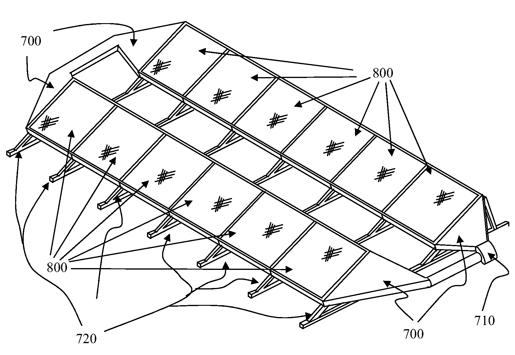
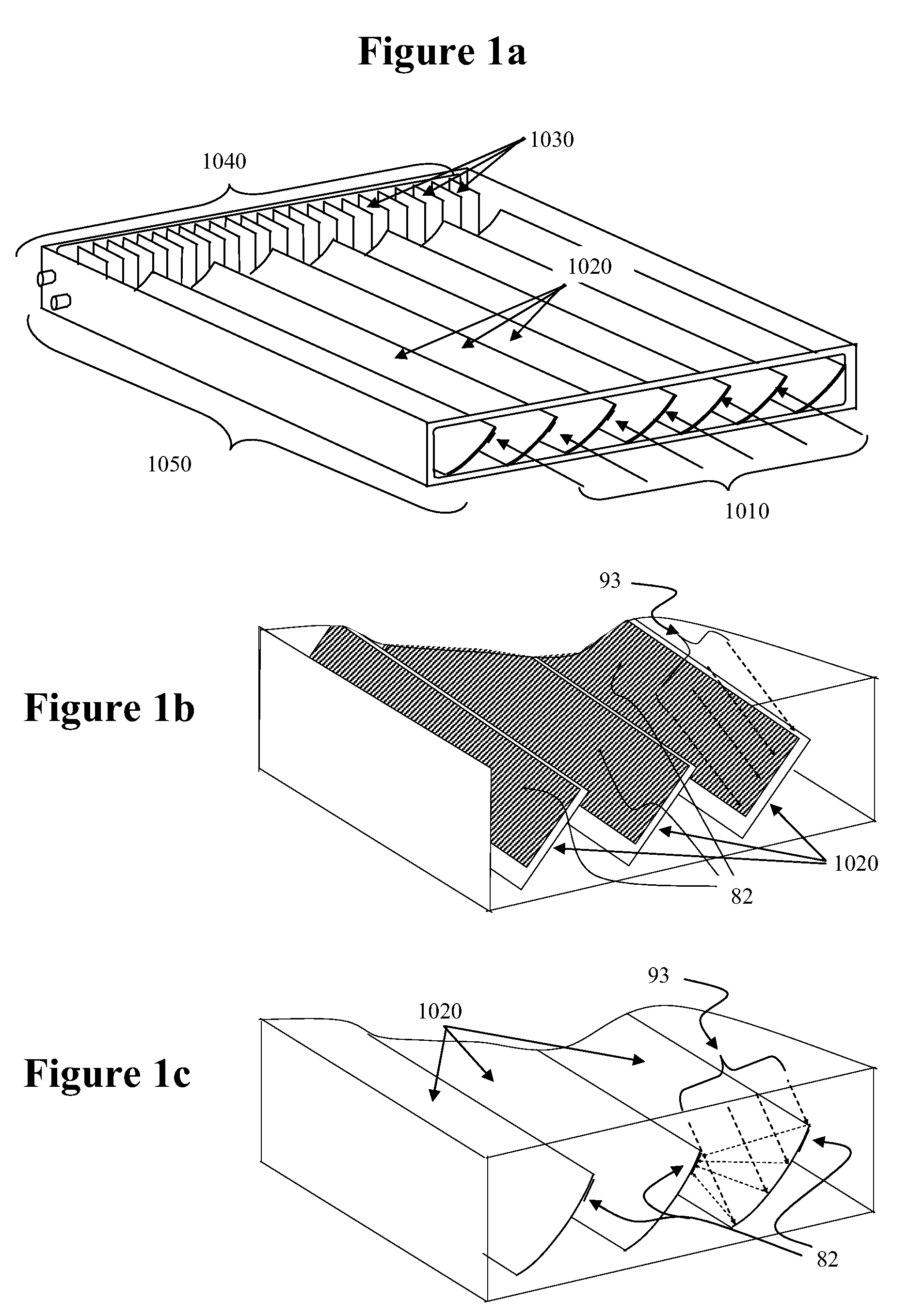
[0033]Embodiments utilize an innovative two-dimensional radiant energy converter (“converter”) that is built in a variety of configurations, incorporated into larger structures and controlled in useful ways to lower the cost and increase efficiency of electromagnetic energy (e.g. sunlight) collection and conversion. Broadly speaking, the energy converter comprises coordinately positioned slats that form a face for admitting light that is transparent to electromagnetic energy, such as sunlight. Embodiments of the converter convert radiant energy that pass through the transparent surface into electricity and / or heat in a variety of innovative conformations, based on reflection and / or absorption on slat surfaces within the converter. Energy is removed as heat from the energy converter, and optionally as electricity. The opposite face of the converter may be transparent or may be absorbent, and the converter may control the amount of radiant energy that passes through unabsorbed. In an ...


PUM


Abstract

Methods and devices are presented that allow the harvest of electricity, heat and lighting simultaneously from a solar converter, often at less cost than conventional solar collectors. The converters use slats to intercept sunlight. Slat surfaces in the direct light path may be coated with photovoltaic (PV) material, or may be shaped to concentrate sunlight, allowing less PV material to capture reflected, concentrated light for improved economics. Forcing air flow past enclosed slats let the slats operate as PV heat sinks, heat absorbers, and heat exchangers capturing much of the solar energy that is not converted to electricity, as heat. Embodiments also allow passage of indirect light to supplement interior artificial lighting, often with positive aesthetic effects. These slatted apertures mitigate glare and overheating problems associated with typical skylights and some windows, allowing wider use as architectural elements. The devices also can be integrated into new building construction, and serve a dual purpose as building structural components.

Description

RELATED APPLICATIONS[0001]This application claims priority based from prior PCT application No. PCT / US07 / 73135 filed on Jul. 10, 2007, and US provisional Application No. 60 / 819,379 filed on Jul. 10, 2006, the entire contents of each are incorporated herein by reference.FIELD OF THE INVENTION[0002]The invention relates to radiant energy conversion devices generally, to the capture and conversion of solar energy into heat and electricity and to building design and control of energy conversion and usage systems.BACKGROUND OF THE INVENTION[0003]Solar generation and cogeneration systems are becoming a logical alternative or addition to fossil fueled energy systems as fuel costs increase. The solar heat that is simultaneously collected with electricity provides a major boost to an energy system's value. Unfortunately, however “solar cogeneration” systems need to be located at the site of use, which presents challenges to most existing or previous photovoltaic concentrator methods. Since t...

Claims


Application Information

Patent Timeline
Patent Type & Authority Applications(United States)
IPC IPC(8): H01L31/052F24S10/30F24S23/70
CPCF24J2/0433H02S40/44F24J2/30F24J2/40F24J2/5239F24J2/541F24J2002/0411F24J2002/1014F24J2002/108F24J2002/5468Y02B10/14Y02B10/20Y02B10/70Y02E10/44Y02E10/47Y02E10/52Y02E10/60H01L31/0521H01L31/0547F24J2/10F24S20/63F24S23/70F24S10/30F24S50/00F24S25/16F24S30/425F24S2020/183F24S2023/832F24S2023/872F24S2030/136Y02B10/10H01L31/052
Inventor FRAZIER, SCOTTDEATON, RIK
Owner MBC VENTURES INC
Why Eureka
Try Eureka