Brake rotor with embedded loose-mass damper system

a technology of loose mass damper and brake rotor, which is applied in the direction of shock absorbers, brake discs, brake drums, etc., can solve the problems of increasing increasing the friction of the rotor, so as to improve the damping method, and reduce the oscillation of the rotating member.

Active Publication Date: 2009-07-09
WOLVERINE ADVANCED MATERIALS
View PDF13 Cites 21 Cited by
  • Summary
  • Abstract
  • Description
  • Claims
  • Application Information

AI Technical Summary

Benefits of technology

[0014]According to another aspect of the present invention, a brake assembly is provided for use with a motorized vehicle that has one or more wheels. The brake assembly includes a rotor having an annular rim portion with a flange portion extending generally orthogonally from an inner peripheral edge thereof. The annular rim portion has a first contact face substantially opposing a second contact face. The rotor is rotatably mounted to the vehicle via the flange portion such that the rotor is operable to transmit braking forces to the vehicle wheel(s). A housing member is mounted proximate to the rotating member. One or more friction members are disposed within the housing member and configured to frictionally engage the rotor. An urging member is also disposed within the housing member, and configured to selectively effect the frictional engagement between the friction members and the rotor. A plurality of loose-mass damper systems is interposed between the first and second contact faces and operable to dissipate kinetic energy directly therefrom.
[0015]According to yet another aspect of the present invention, an improved method of damping noise produced by a vehicle brake system is provided. The brake system includes a forcing member configured to operatively engage a friction member with a rotating member. The rotating member has an annular rim portion with first and second substantially opposing contact faces. The method includes the step of: reducing oscillation of the rotating member by interposing a loose-mass damper system between the first and second contact faces to thereby dissipate kinetic energy directly therefrom. Preferably, the method also includes embedding a plurality of the loose-mass damper systems at preselected locations within the annular rim portion. Each of the plurality of loose-mass damper systems includes at least one mass, such that reducing oscillation of the rotating member includes repeatedly impacting the mass against first and second inner faces respectively opposing the first and second contact faces of the rotor. Reducing oscillation of the rotating member is independent of temperature and pressure.

Problems solved by technology

Additionally, as the brake assembly components heat up, the rotor may develop hot spots.
The hot spots can cause the rotor to have regions of varying depth and friction, producing inconsistent levels of brake torque, and potentially exacerbating the aforementioned brake squeal.
Brake squeal is generally unappealing and unpleasant to vehicle occupants, pedestrians, etc., especially as vehicles are designed to be more comfortable and quieter.

Method used


Image

  • Brake rotor with embedded loose-mass damper system
  • Brake rotor with embedded loose-mass damper system
  • Brake rotor with embedded loose-mass damper system

Examples


Embodiment Construction

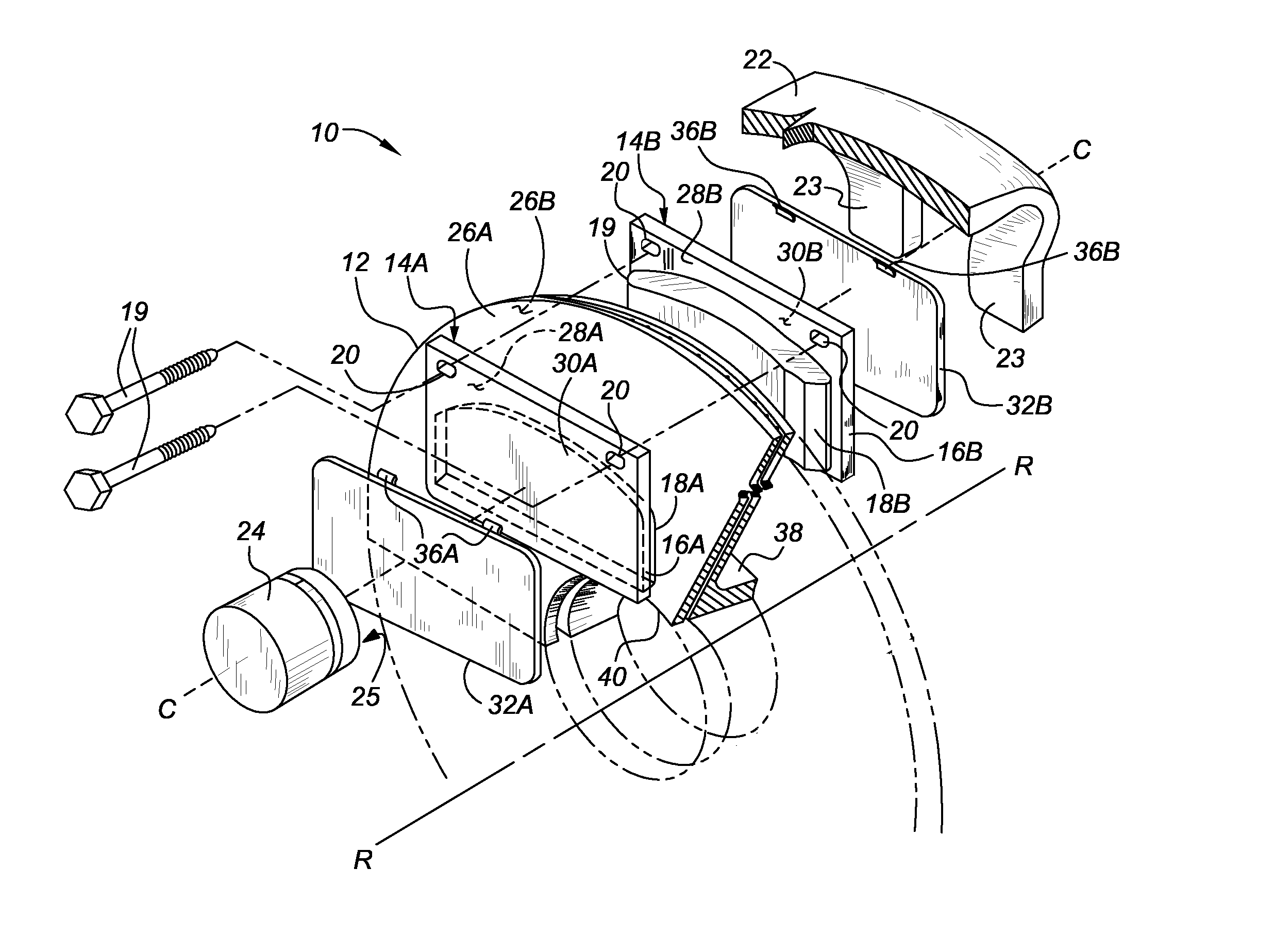
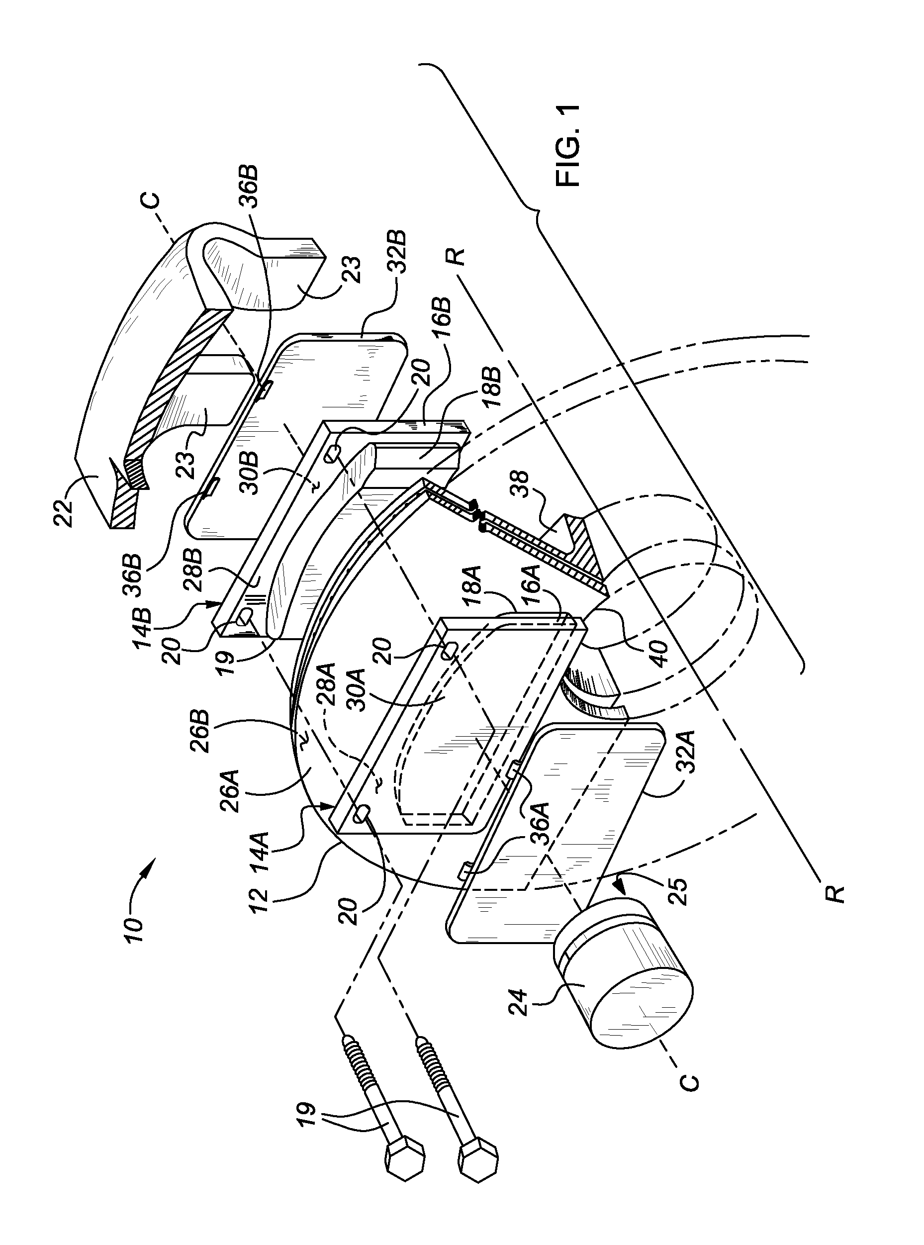
[0025]Referring to the Figures, wherein like reference numbers refer to like components throughout the several views, FIG. 1 is an exploded perspective illustration of a vehicle disc brake assembly, identified generally as 10, in accordance with the present invention. The disc brake assembly 10 is illustrated in FIG. 1 as single-piston, floating-type caliper. However, the present invention may be applied to multiple-piston brake assemblies and fixed-type calipers without departing from the inventive concept described herein. In addition, the application of FIG. 1 is provided merely for explanatory purposes—the constituent members are purely exemplary and the dimensions thereof exaggerated for clarity and for a better understanding of the present invention. As such, the present invention is not intended to be limited to the structure provided in FIG. 1.

[0026]The disc brake assembly 10 of FIG. 1 includes one or more friction members, defined herein by first and second brake pads 14A a...


PUM


Abstract

A rotor is provided for use with a vehicle brake assembly that includes a forcing member operable to urge a friction member into mechanical communication with the rotor to thereby oppose movement of the same. The rotor includes a rotor body with an annular rim portion having first and second opposing contact faces. One or more loose-mass damper systems are interposed between the first and second contact faces, and operable to dissipate kinetic energy directly therefrom. Each of the loose-mass damper systems includes at least one mass operable to repeatedly impact against first and second inner faces respectively opposing the first and second contact faces to reduce oscillation of the rotor. Reducing oscillation of the rotor is independent of temperature and pressure. The loose-mass damper systems are preferably oriented proximate to an outer peripheral edge of the annular rim portion generally circumferentially equidistant from one another.

Description

TECHNICAL FIELD[0001]The present invention relates generally to braking systems for motorized vehicles, and more particularly to devices for minimizing or cancelling vibrations and dampening resultant noise produced by vehicle brake systems.BACKGROUND OF THE INVENTION[0002]Most conventional motorized vehicles, including, but not limited to, automobiles, trucks, buses, construction vehicles, aircraft, etc., are equipped with a brake system for selectively slowing or stopping movement of the vehicle in a controlled manner. Modern automotive braking systems may be grouped into two basic categories, disc brakes and drum brakes. A typical automotive brake system may include a disc brake assembly for each of the front wheels, and either a drum brake assembly or a disc brake assembly for each of the rear wheels. Regardless of type, brake assemblies are normally actuated by hydraulic, pneumatic, or mechanical pressure generated by an operator of the vehicle by, for example, depressing a foo...

Claims


Application Information

Patent Timeline
Patent Type & Authority Applications(United States)
IPC IPC(8): F16D65/12F16D65/02F16D55/224F16F7/00
CPCF16D65/0006F16D65/0018F16F15/145F16D2065/1328F16D65/12
Inventor KAPPAGANTU, RAMANA
Owner WOLVERINE ADVANCED MATERIALS
Why Eureka
Try Eureka