
Undershot impulse jet driven water turbine having an improved vane configuration and radial gate for optimal hydroelectric power generation and water level control

a technology of impulse-jet-driven water turbines and water level control, which is applied in the direction of rotors, vessel construction, greenhouse gas reduction, etc., can solve the problems of uncompetitive electricity generation at very low-head dams, lack of suitable equipment,

Inactive Publication Date: 2009-07-09
BROOME KENNETH R
View PDF3 Cites 18 Cited by
  • Summary
  • Abstract
  • Description
  • Claims
  • Application Information

AI Technical Summary

Benefits of technology

[0013]In accordance with the foregoing and other objectives, an undershot water turbine is provided for placement in a watercourse with or without an impoundment, such as an irrigation canal, or navigable river. The water turbine assembly comprises an automatically adjustable radial gate that optimizes the hydraulic head at the jet and maintains the upstream water level within narrowly defined limits at any predetermined elevation, thereby providing watershed sustainability—a feature of significant value in irrigated areas served by gravity flow from the canal.
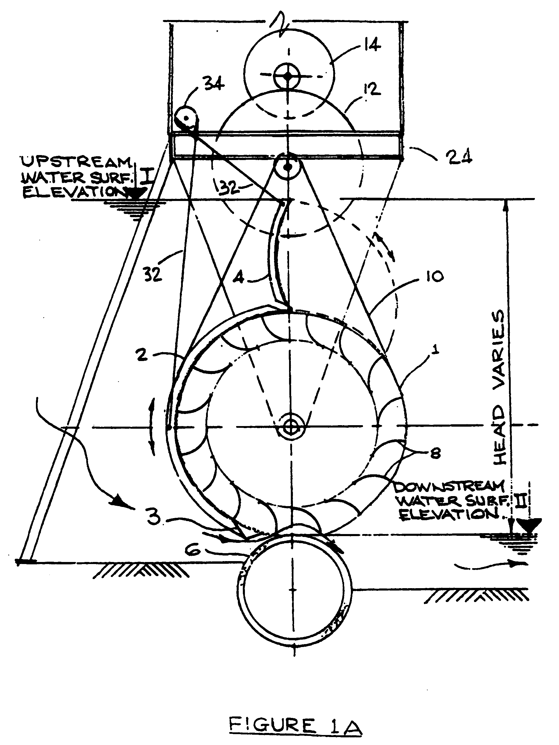
[0017]The shape of the sole plate is curved to conform to the boundary conditions favoring minimum expansion of the jet as it impinges on each vane of the-water turbine. The sole plate in conjunction with the shape of the radial gate forms the jet in a hydraulically efficient way such that the emerging jet is optimized and without expansion, thereby increasing the kinetic energy transferred from the water jet into the vanes of the turbine.
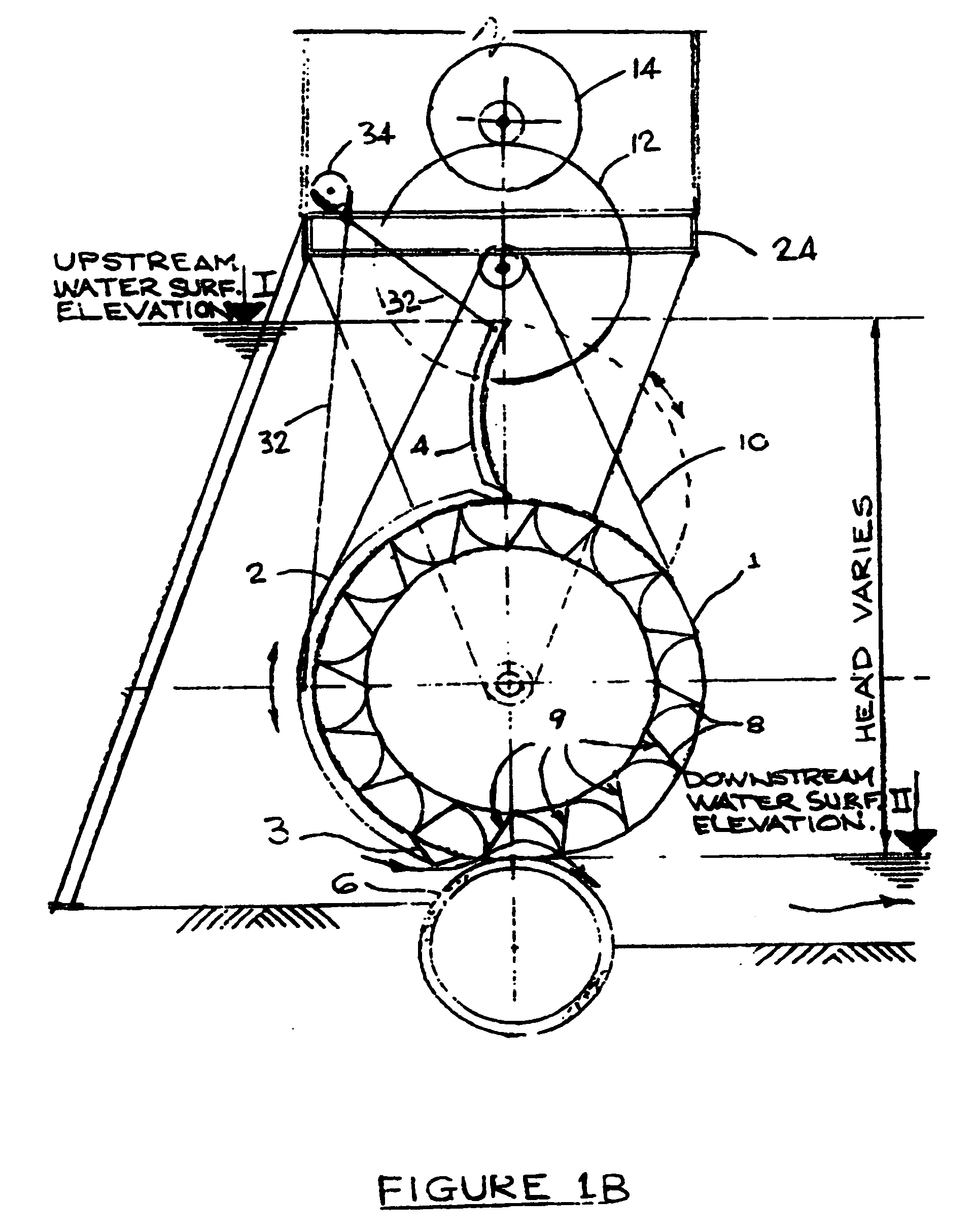
[0018]The water turbine comprises a rotor having a longitudinal axis disposed substantially perpendicular to the flow of the jet. A series of curved vanes are provided substantially in parallel with the longitudinal axis of the rotor and disposed radially about the rotor's surface, such that a major surface or leading edge of each vane is disposed for substantially perpendicular alignment with respect to the flow vector of the jet. In accordance with an aspect of the invention, the leading edge of each vane is provided with a stiffening element, such as a support plate, that forms a continuous flow control surface extending from the leading edge of each vane to the base of a successive vane. In rotation, the support plate's control surface establishes approach conditions for the jet as it successively impacts each vane, and defines a streamlined flow path for the jet, such that turbulence and vortices in the jet are substantially eliminated as the jet approaches the leading edge of each successive vane. This has been found to increase advantageously the amount of kinetic energy that can be extracted from the jet. Efficiencies of about 85 percent may be realized. See Appendix A page 13, CFD Analysis of An Undershot Impulse Jet Hydropower Generator, University of Iowa, Nov. 11, 2008; incorporated herein by reference. Such an arrangement also stiffens the rotor and reduces the need for a separate core pipe.
[0019]A hinged flap can be attached to the upper edge of the radial gate in order to increase the effective pressure at the elevation of the jet beyond the diameter of the wheel itself. This flap can be adjusted to achieve maximum upstream water level at any position of the radial gate and is curved to the same radius as the radial gate such that is can be lowered to discharge flows in the waterway that are higher than can be passed through the water turbine under the radial gate.
[0021]An additional aspect of the invention maintains a desired upstream water surface elevation by locally or remotely opening or closing the radial gate and superposed flap, regardless of stream flow within the limits of the design. The purpose of maintaining the desired upstream water surface elevation advantageously enables control of water surface elevations in irrigation canals and navigable rivers. This can avoid flooding and can achieve gravity flow into selected adjacent irrigation systems as well as maintaining necessary minimum depth for navigation. Control of water surface elevations in irrigation canals is a primary operational constraint that in many existing canals is achieved by raising or lowering the tops of weirs formed by manually placing or removing wooden boards one on top of another in slots supported by steel posts or concrete abutments.
[0022]This aspect of the invention includes the installation of automatic or remotely controlled radial gates on a series of water turbines disposed throughout a watershed or irrigation system to control water flow automatically throughout such a system for optimal watershed management. The automatic control system becomes financially feasible by means of the source of revenue derived from the sale of electric power in addition to the saving in the cost of labor necessary to manually adjust the height of weir boards.

Problems solved by technology

Generation of electricity at very low-head dams (less than about 15 feet difference between water levels upstream and downstream of a dam) has become uncompetitive with other forms of electric power generation.
This is due to a lack of suitable equipment that can be installed for a total capital cost per kilowatt of capacity lower than that of other forms of generation from renewable sources, such as wind power, wave power and solar energy that have no fuel costs.
There have been two problems with this approach however.
First, the volume of water required to develop the same power output increases inversely to the reduction in head, thereby requiring larger diameter equipment and greater amounts of excavation and concrete for the water passages, all at progressively higher cost for diminishing revenue.
Secondly, the proportions of cost required to construct the civil works actually increases faster than the cost of the equipment.
As previously mentioned, however, at very low heads, the cost of both equipment and the civil works needed for conveying water to and from the equipment increases disproportionately in comparison to the value of power produced.
Using presently available equipment and installation methods results in the cost of power becoming uncompetitive at hydraulic head differences less than about 15 feet.
Up to now, conventional very low head hydro generation systems have been uneconomic power sources, and are not competitive with other forms of non fuel based energy production such as wind, wave or solar power.
Conventional low head hydro equipment systems focus on increasing efficiency, resulting in increased manufacturing and installation costs.
Efficiency is not the economic key to success.

Method used


Image

  • Undershot impulse jet driven water turbine having an improved vane configuration and radial gate for optimal hydroelectric power generation and water level control
  • Undershot impulse jet driven water turbine having an improved vane configuration and radial gate for optimal hydroelectric power generation and water level control
  • Undershot impulse jet driven water turbine having an improved vane configuration and radial gate for optimal hydroelectric power generation and water level control

Examples


Embodiment Construction

[0037]Design of the water turbine and vanes and the location of speed increaser and generator in coaxial arrangement within the hub of the water turbine are described in U.S. Pat. No. 5,440,175, “water turbine-Driven Generating Unit,” and in U.S. Pat. No. 6,208,037, “water turbine-Driven Generating Assembly,” which are incorporated herein by reference.

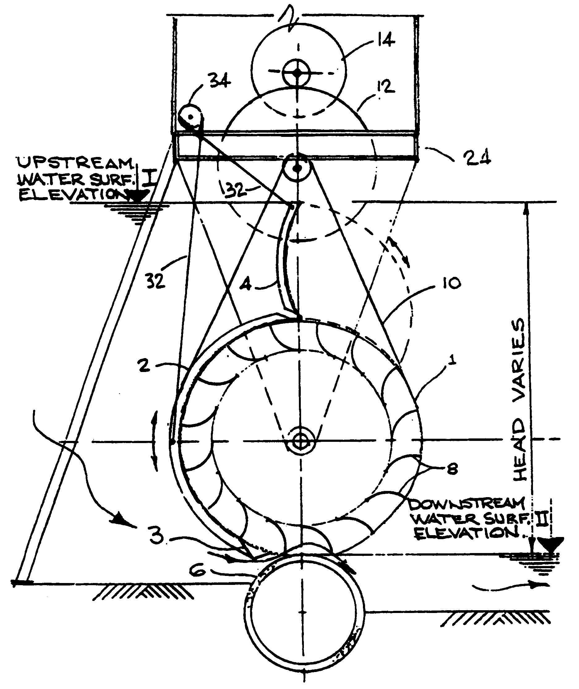
[0038]Referring to the drawings, FIG. 1A shows a water turbine comprising a rotor 1 with a radial gate 2, a moveable flap gate 4, and sole plate 6 for directing water flow together with the radial gate 2 into a plurality of vanes 8 disposed radially about the rotor 1. A chain drive 10 is coupled with a speed increaser 12 and spur gear arrangement that provides an appropriate speed for generator 14. Preferably the speed increaser 12 is an epicyclical sun and planetary gear arrangement, which takes the speed of rotation of water wheel 1 and converts it to a useful speed for the generator, for example 1800 rpm. The speed increaser can pro...


PUM


Abstract

A low-head impulse jet water turbine for electric power generation at irrigation canal drop structures, navigation dam spillways or other low head watercourses achieves renewable electric power generation at competitive cost. Kinetic energy of a low-pressure jet is employed in a way that enables numerous locations to generate electricity conveniently near points of use, from a renewable source at minimum cost. The equipment can be pre-assembled for minimum installation cost at sites with no existing impoundment and can be automatically raised clear of flood levels with built-in lifting equipment. Existing multi-span bridges offer convenient access for installation and maintenance. The system for raising the equipment also provides clear passage for fish migration.

Description

CROSS REFERENCE TO RELATED APPLICATION[0001]This application is a continuation in part of U.S. Ser. No. 11 / 244,453, filed on Oct. 6, 2005.REFERENCE TO APPENDIX[0002]The attached CFD Analysis of An Undershot Impulse Jet Hydropower Generator, University of Iowa, Nov. 11, 2008, provides an independent computational fluid dynamics analysis of features and aspects of the present invention and is submitted as Appendix A, and incorporated herein by reference.BACKGROUND[0003]1. Field of the Invention[0004]The field of the invention generally relates to hydroelectric power generation. In particular, the field of the invention relates to an undershot impulse-jet driven water turbine for generating a useful amount of electric power from a low head dam in watercourses such as an irrigation canal or a navigable river, or even in a watercourse without the need for a dam. A water turbine assembly comprises an automatically adjustable radial gate and hinged upper flap to maximize the hydraulic head...

Claims


Application Information

Patent Timeline
Patent Type & Authority Applications(United States)
IPC IPC(8): F03B15/06F03B13/10
CPCF03B1/00Y02E10/223F05B2240/241F03B7/003Y02E10/20
Inventor BROOME, KENNETH R.
Owner BROOME KENNETH R
Learn More