Torque Transmission Device Useful as a Fixed Constant Velocity Ball Joint Constructed as an Opposed Track Joint and Method for Producing Such a Joint

a transmission device and constant velocity technology, applied in the direction of couplings, mechanical equipment, rotary machine parts, etc., can solve the problems of high cost, long machining time, large waste and quality loss in regard to strength, etc., and achieve high hardness, rapid and efficient production, and low cost

Inactive Publication Date: 2009-07-09
NEUMAYER TEKFOR HLDG GMBH
View PDF10 Cites 4 Cited by
  • Summary
  • Abstract
  • Description
  • Claims
  • Application Information

AI Technical Summary

Benefits of technology

[0053]At relatively low cost and without requiring provision of special machines, the invention ensures rapid and efficient production of the longitudinal teeth with sufficiently high hardness and also a correspondingly high strength and, by the possibility of using the so-called soft broaching, the production of longitudinal teeth having higher precision and service life.

Problems solved by technology

The chip-removing production according to U.S. Pat. No. 6,872,143 is primarily complex, and requires costly machines and long machining times. It also causes significant waste and quality losses in regard to the strength, because the material flow lines in a joint internal or external part produced as a preform by forging, are cut through by the machining.
The precision of the parts is also limited by the guiding precision of the machine.
The unavoidable indexing irregularity in the preform also can no longer be remedied in the following machining steps.

Method used


Image

  • Torque Transmission Device Useful as a Fixed Constant Velocity Ball Joint Constructed as an Opposed Track Joint and Method for Producing Such a Joint
  • Torque Transmission Device Useful as a Fixed Constant Velocity Ball Joint Constructed as an Opposed Track Joint and Method for Producing Such a Joint
  • Torque Transmission Device Useful as a Fixed Constant Velocity Ball Joint Constructed as an Opposed Track Joint and Method for Producing Such a Joint

Examples


Embodiment Construction

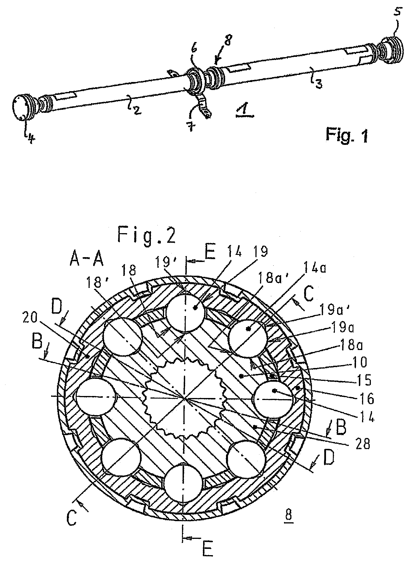
[0066]The driveshaft 1 shown in FIG. 1 is constructed here as a longitudinal driveshaft of a motor vehicle and comprises two partial shafts 2 and 3, which carry connection parts 4, 5 on their free ends. These connection parts are constructed as flexible rubber couplings, although cardan joints may also be fastened to the cited partial shafts 2 and 3 in their place, as described in US 2006 / 014587 or U.S. Pat. No. 6,893,352 (=DE 100 32 853).

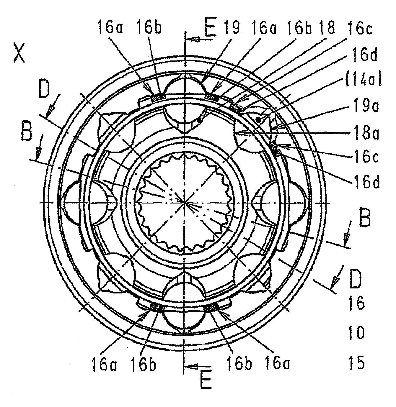
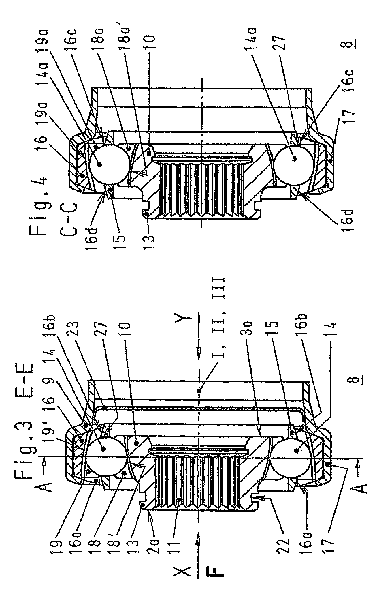
[0067]The two partial shafts 2 and 3 are connected to one another via a cardan joint 8, which is shown in various sectional illustrations in FIGS. 2 through 8, approximately in the middle of the drive configuration 1. In addition, FIG. 1 shows that the left partial shaft 2 is fastenable to the underbody of a motor vehicle via an intermediate bearing 6 and a retainer 7 situated thereon.

[0068]As can be seen in particular from the sections according to FIGS. 2 through 6 and FIG. 9, which show the cardan joint 8 not connected to the partial shafts 2 an...


PUM

PropertyMeasurementUnit
velocityaaaaaaaaaa
structureaaaaaaaaaa
hardnessaaaaaaaaaa

Abstract

A torque transmitting device, such as a fixed constant velocity ball joint as a counter track joint and a method for producing such a joint, in which the curvatures of the bases of the joint tracks deviate in their axial course from the curvatures of the ball contact lines. The method is characterized in that the joint component is brought to an increased hardness by a hardening process prior to the formation of the longitudinal profile of the component, and a diffusion layer is partially or completely removed in the region of the longitudinally profiled structure.

Description

CROSS REFERENCE TO RELATED APPLICATIONS[0001]This application is a continuation of international patent application no. PCT / DE2007 / 001194, filed Jul. 5, 2007 designating the United States of America and published in German on Jan. 10, 2008 as WO 2008 / 003306, the entire disclosure of which is incorporated herein by reference. Priority is claimed based on Federal Republic of Germany patent application nos. DE 10 2006 031 002, filed Jul. 5, 2006; DE 10 2006 037 847, filed Aug. 12, 2006 and DE 10 2007 030 898, filed Jul. 3, 2007.BACKGROUND OF THE INVENTION[0002]The invention relates to torque transmission devices, such as fixed, constant velocity ball joints as opposed track joints having[0003]a joint external part having external tracks,[0004]a joint internal part having internal tracks,[0005]torque-transmitting balls, which are accommodated in track pairs made of external tracks and internal tracks,[0006]a ball cage having cage windows, in which balls are retained and guided upon defl...

Claims


Application Information

Patent Timeline
Patent Type & Authority Applications(United States)
IPC IPC(8): F16D3/02F16D3/10B21K1/06F16D3/224
CPCB23P2700/11F16D3/224F16D2001/103F16D2003/22306F16D2250/00Y10T29/49689Y10S464/906Y10T403/7035Y10T29/49636Y10T29/49826F16D2300/10F16D3/20F16D3/22
Inventor SZENTMIHALYI, VOLKERLUTZ, MATHIASKOERNER, EKKEHARD
Owner NEUMAYER TEKFOR HLDG GMBH
Why Eureka
Try Eureka