

Fracture prediction method, device, a program arrangement and computer-accessible medium therefor
- Summary
- Abstract
- Description
- Claims
- Application Information
AI Technical Summary
Benefits of technology
Problems solved by technology
Method used
Image

Examples
first exemplary embodiment
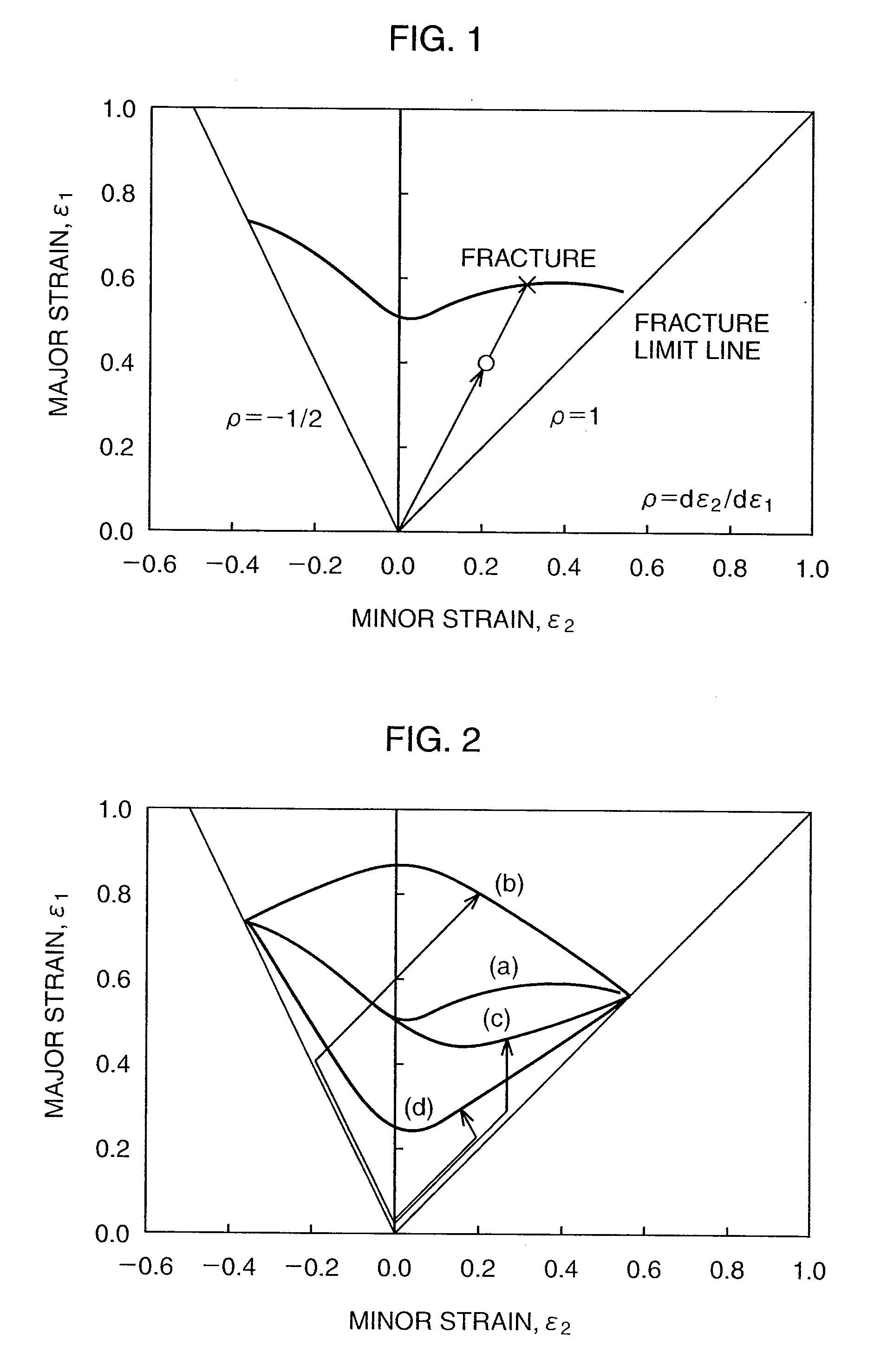
[0056]A margin against a fracture when evaluating formability is determined in general using a thinning criterion or an FLD, which can be used for fracture prediction in a car crash analysis as well. Among them, the FLD is known to vary largely depending on a strain path changes, and cannot be expected to have high prediction accuracy as a method of evaluating a fracture in a plastic deformation process, in which the deformation path varies largely as in crash of an automobile body part subjected to press-forming or pre-deformation in press-forming.
[0057]However, recently Kuwabara et al. (e.g., described in Journal of the Japan Society for Technology of Plasticity, 45, 123, 2004; and Non-patent Document 2: CAMP-ISIJ 17, 1063, 2004) verified by experiment and analysis that, using a fracture limit curve expressed in stress space with an aluminum extruded material or mild steel sheets being the subject, the fracture limit can be represented almost uniquely without depending on the path...
second exemplary embodiment
[0123]Conventionally, the margin against a fracture is often evaluated by a thinning, but due to popularization of numerical simulations and advancement in functions of post-processing software, fracture evaluation methods using a forming limit diagram (FLD) are started to be used widely. The FLD can be obtained by an experiment such as the Nakajima method. However, such a method is complicated, and it is difficult to construct a database for various types of steel sheet menus and thickness. Thus, several prediction approaches have been proposed.
[0124]For example, in post-processing functions of general-purpose software, there can be incorporated a method (as described in Journal of the Japan Society for Technology of Plasticity, 45, 123, 2004) in which a Keeler's thickness correction empirical rule is added to the Hill's localized necking model and the Swift's diffuse necking model. However, prediction values obtained with these theories may allow for a prediction for aluminum or m...
example 1
[0130]First, an exemplary method of measuring the FLD of strain space experimentally is described. The fracture limit strain can be measured by a proportional loading experiment with a steel sheet constituted of a metal material having mechanical property values and material parameters shown in Table 1 below being the subject. Here, t represents the thickness of a thin plate, YP represents proof strength, TS represents ultimate tensile strength, U.E1 represents uniform elongation, E1 represents total elongation, rm represents average r value (indicating a Lankford value and is expressed by rm=(r0+2r45+r90) / 4 where r value in the rolling direction is r0, r value in the 45° direction with respect to the rolling direction is r45, and r value in the 90° direction with respect to the rolling direction is r90), and K, ε0, n represent material parameters obtained when a stress-strain curve obtained from a uniaxial tensile test is fitted in a function expression:
[Equation 17]
σeq=K(εeq+ε0)n ...
PUM
 Abstract
Description
Claims
Application Information