Pade' approximant based compensation for integrated sensor modules and the like

Inactive Publication Date: 2005-11-17
SEMICON COMPONENTS IND LLC
View PDF11 Cites 36 Cited by
  • Summary
  • Abstract
  • Description
  • Claims
  • Application Information

AI Technical Summary

Benefits of technology

[0028] The present invention provides a nonlinearity compensation method and a corresponding structure that can be made highly accurate, can be programmably adjusted, and can be made flexible so as to be used in a wide range of applications while allowing for low cost mass production and reduced power consumption. Methods and structures disclosed herein allow for sensor calibration

Problems solved by technology

Many sensing elements present unique requirements and limitations that need to be somehow circumvented or compensated for.
Often, the electric or other signal generated by a sensor in response to a given physical attribute that is being sensed (e.g., force, displacement, velocity, acceleration, temperature or any other physical parameter that can be detected and/or measured) is comparatively weak, distorted, or simply not adequate to interface directly with the electronic or other control system that is to use the sensor output signal.
The non-ideal response functions may be plagued by variation of response over different temperature ranges and/or by nonlinear response to linear change in the physical parameter being measured.
Although a number of different nonlinearity compensation techniques have been developed, they tend to be costly and time consuming to implement and frequently provide insufficient accuracy or suffer from other undesirable technical limitations.
Although the technique is effective to varying degrees, these source feedback techniques rely on manual, trial-and-error adjustments with use of potentiometers or selection of resistors with pre-selected values.
This kind of approach is not adequate to mass production where each

Method used


Image

  • Pade' approximant based compensation for integrated sensor modules and the like
  • Pade' approximant based compensation for integrated sensor modules and the like
  • Pade' approximant based compensation for integrated sensor modules and the like

Examples


embodiment 1000

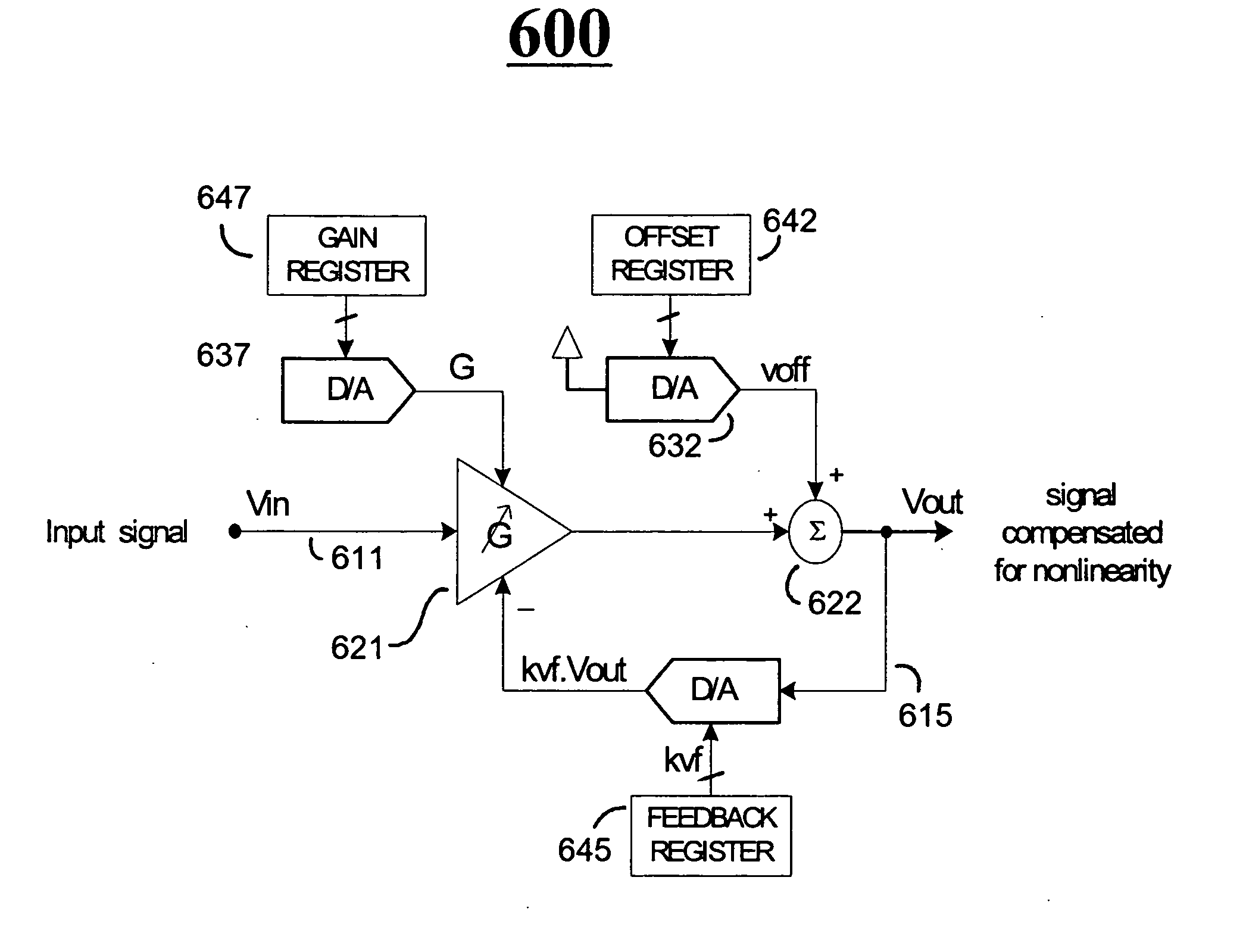
[0099] Although it is better suited to be implemented by a programmable analog integrated circuit, the invented method for nonlinearity compensation can also have a digital embodiment if the input variable Vin is a digital signal. FIG. 10 shows a digital embodiment 1000 that is roughly equivalent to the analog embodiment of FIG. 6.

[0100]FIG. 12 is a schematic of yet another sensor module 1201 in accordance with the disclosure. The to-be-sensed physical parameter, P(t), is coupled into the module 1201 from the external environment 1200. Coupling may be accomplished wirelessly, such as by magnetic and / or electrostatic coupling. In response to the coupled physical parameter, P(t), a corresponding primary sensor 1205 generates a corresponding, sensor output signal, x(t). In some embodiments, an excitational signal e(t) may be additionally coupled to the primary sensor 1205 from an in-module excitation source 1265. The excitational signal e(t) may be used for causing the sensor 1205 to o...

embodiment 1500

[0116]FIG. 15 is a schematic of an embodiment 1500 having a digital input multiplier (the leftmost D / A converter) at the front end of the mapping circuit and a further digital multiplier receiving feedback from the output.

embodiment 1600

[0117]FIG. 16 is a schematic of a further embodiment 1600 having a 3-input multiplier at the front end of the mapping circuit and 3-input summer before the variable gain amplifier.


PUM


Abstract

Methods and systems using Pade′ Approximant expansion ratios provide mappings between nonlinear sensors and a more linearized output domain. In one embodiment (a) a variable gain amplifier receives a supplied input signal, the amplifier has at least a first input terminal, an output terminal, and a gain control terminal; (b) a first summer coupled to the output terminal of the variable gain amplifier adds in a first offset signal; (c) a first multiplier coupled to an output of the first summer receives a proportional feedback factor signal and correspondingly generates a multiplied feedback; (d) a second summer coupled to an output terminal of the first multiplier adds in a corresponding second offset signal; and (e) a second multiplier coupled to an output of the second summer receives a gain factor signal and generates a multiplied gain signal; where the gain control terminal of the variable gain amplifier is operatively coupled to an output terminal of the second multiplier.

Description

FIELD OF DISCLOSURE [0001] The present invention relates generally to electronic systems which compensate for analog transducer nonlinearities and / or temperature drift. [0002] More specifically, the invention relates to integrated sensor modules where a transducer is packaged together with compensating means such as electronic compensating circuitry. CROSS REFERENCE TO PATENTS [0003] The disclosures of the following U.S. patents are incorporated herein by reference: [0004] (A) U.S. Pat. No. 6,198,296, issued Mar. 6, 2001 to Ivanov and entitled “Bridge sensor linearization circuit and method”; [0005] (B) U.S. Pat. No. 5,902,925, issued May 11, 1999 to Crispie et al. and entitled “System and method for high accuracy calibration of a sensor for offset and sensitivity variation with temperature”; [0006] (C) U.S. Pat. No. 5,848,383, issued Dec. 8,1998 to Yunus and entitled “System and method for precision compensation for the nonlinear offset and sensitivity variation of a sensor with te...

Claims


Application Information

Patent Timeline
IPC IPC(8): G01D3/02G01D3/028G06F19/00
CPCG01D3/028G01D3/022
Inventor LARAIA, JOSE MARCOSTAVEIRA, JOSE G.MOEHRKE, ROBERT P.
Owner SEMICON COMPONENTS IND LLC
Why Eureka
Try Eureka