
Method and system for reducing turn around time of complicated engineering change orders and asic design reutilization

a technology of engineering change orders and engineering change orders, applied in the direction of cad circuit design, program control, instruments, etc., can solve the problems of high risk, inefficient generating a new netlist for pd after a design freeze, and difficult to solve critical timing/pd parameters. , to achieve the effect of reducing the turn around time of engineering change orders

Inactive Publication Date: 2009-07-09
GLOBALFOUNDRIES INC
View PDF2 Cites 17 Cited by
  • Summary
  • Abstract
  • Description
  • Claims
  • Application Information

AI Technical Summary

Benefits of technology

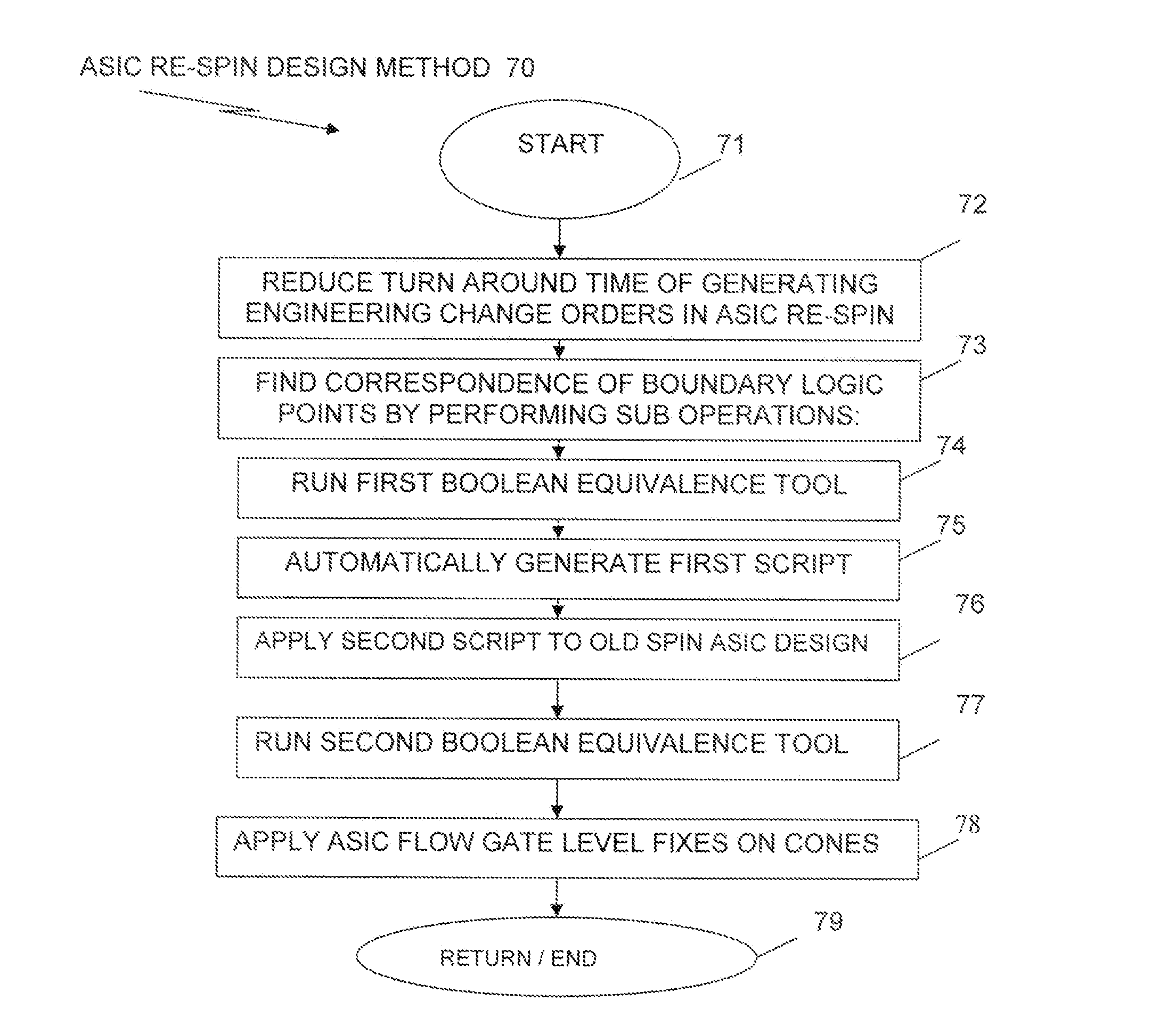
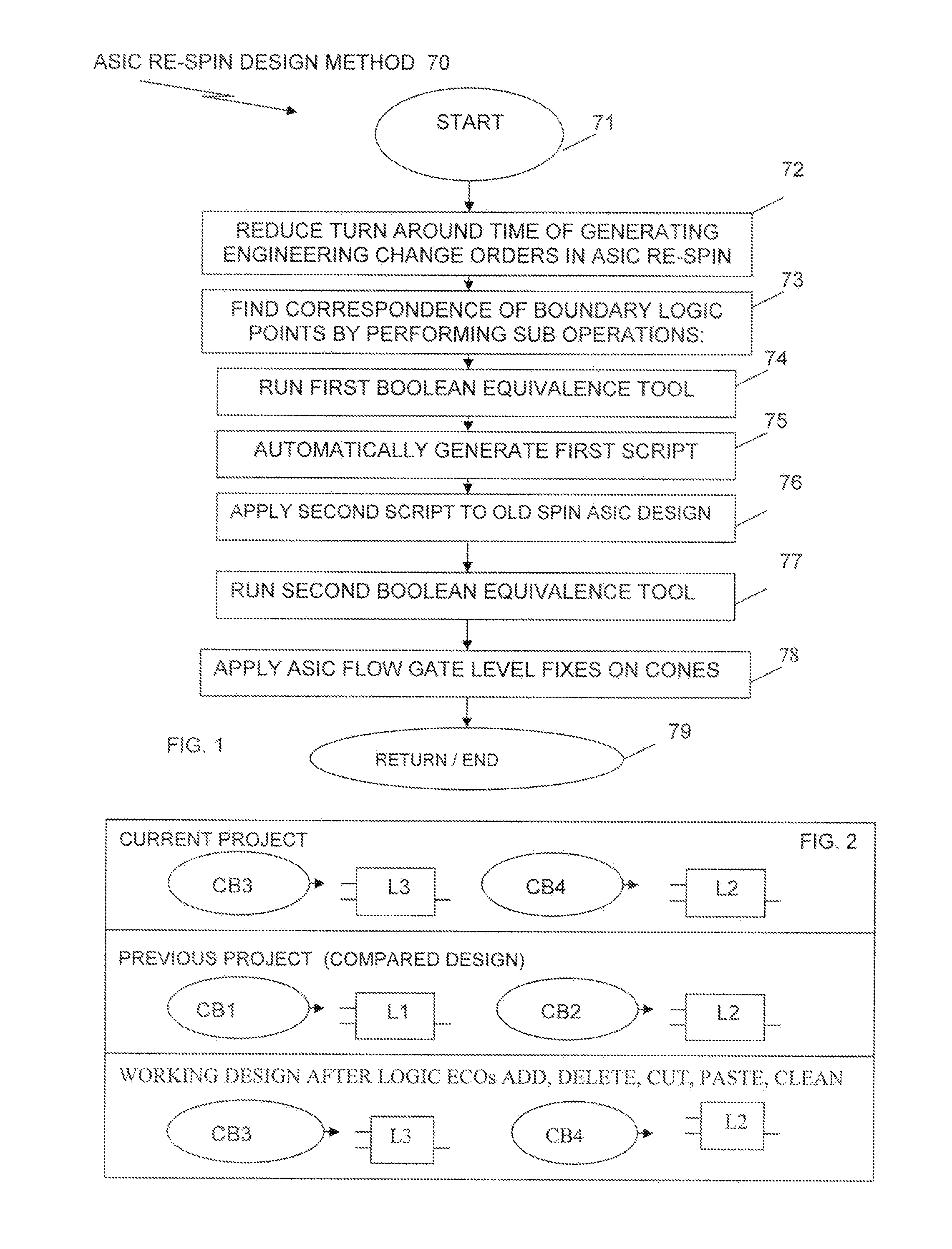
[0003]A method, and system are disclosed herein for reducing turn around time of engineering change orders when performing ASIC re-spin designs. Computer executable program code in a local computer which is part of a computer system, causes the local computer to find, contemporaneously, all corresponding boundary points of storage gate elements indicted by engineering change orders to be either added, deleted, or modified. The group of engineering change orders includes a group of scripts that are applied to a reliability test chip (RTC) starting point design and a new post front end processing design, and wherein the finding operation performs the sub operations of running a first Boolean equivalence tool between an old spin ASIC design and a new ASIC design netlist. A first generating sub operation, automatically generates a first script from the group of scripts including a first group of storage gate elements that were either added, deleted, or modified or renamed on an old ASIC spin design and saves the new netlist as the new re-spin ASIC design. The first group of storage gate elements includes one or more of FLOPs, arrays and built-in-self-test gates. The first script includes the first group of gate elements added, deleted and / or modified that caused a failing model correspondence because of uncorrespondence between the old spin ASIC design and the new re-spin ASIC design. A second script is applied to the old spin ASIC design to obtain a new design netlist and the new design netlist ASIC design is saved as a new re-spin ASIC design. A second Boolean equivalence tool is run between the new design netlist and the new re-spin ASIC design to obtain all falling boundary storage gate elements and to perform cutting, pasting deleting, modifying and / or renaming all failing boundary storage gate elements to pass correspondence tests. And, after running a cleanup operation, an applying operation, applies ASIC flow gate level fixes to cloned synthesized storage gate elements.

Problems solved by technology

It is desirable to preserve some portions of the chip which are timing / PD critical and it is difficult to solve critical timing / PD parameters from the previous spin in terms of time, production yield (PY) and expertise needed; this results in high risks, in regard to meeting schedules, because of the need to spend time in duplicating efforts of solving those critical portions from the previous spin, where additional PY and expertise are needed from the previous spin.
An engineering change order (ECO) is needed to update any design freeze, so as to match re-synthesized code, because generating a new netlist for PD after a design freeze is inefficient, because of the loss of PD work.
Furthermore, manually describing the necessary changes at the gate level is a time-consuming, error prone, iterative task; and there is no known way of automatically identifying and listing all of the desired boundary logic points that are needed to be implemented in an engineering change order for all design changes in a re-spin of an ASIC design.

Method used


Image

  • Method and system for reducing turn around time of complicated engineering change orders and asic design reutilization
  • Method and system for reducing turn around time of complicated engineering change orders and asic design reutilization
  • Method and system for reducing turn around time of complicated engineering change orders and asic design reutilization

Examples


Embodiment Construction

[0009]The exemplary embodiment of the invention is described below in detail. The disclosed exemplary embodiment is intended to be illustrative only, since numerous modifications and variations therein will be apparent to those of ordinary skill in the art. In reference to the drawings, like numbers will indicate like parts continuously throughout the view. Further, the terms “a”, “an”, “first”, “second” and “third” herein do not denote a limitation of quantity, but rather denote the presence of one or more of the referenced item.

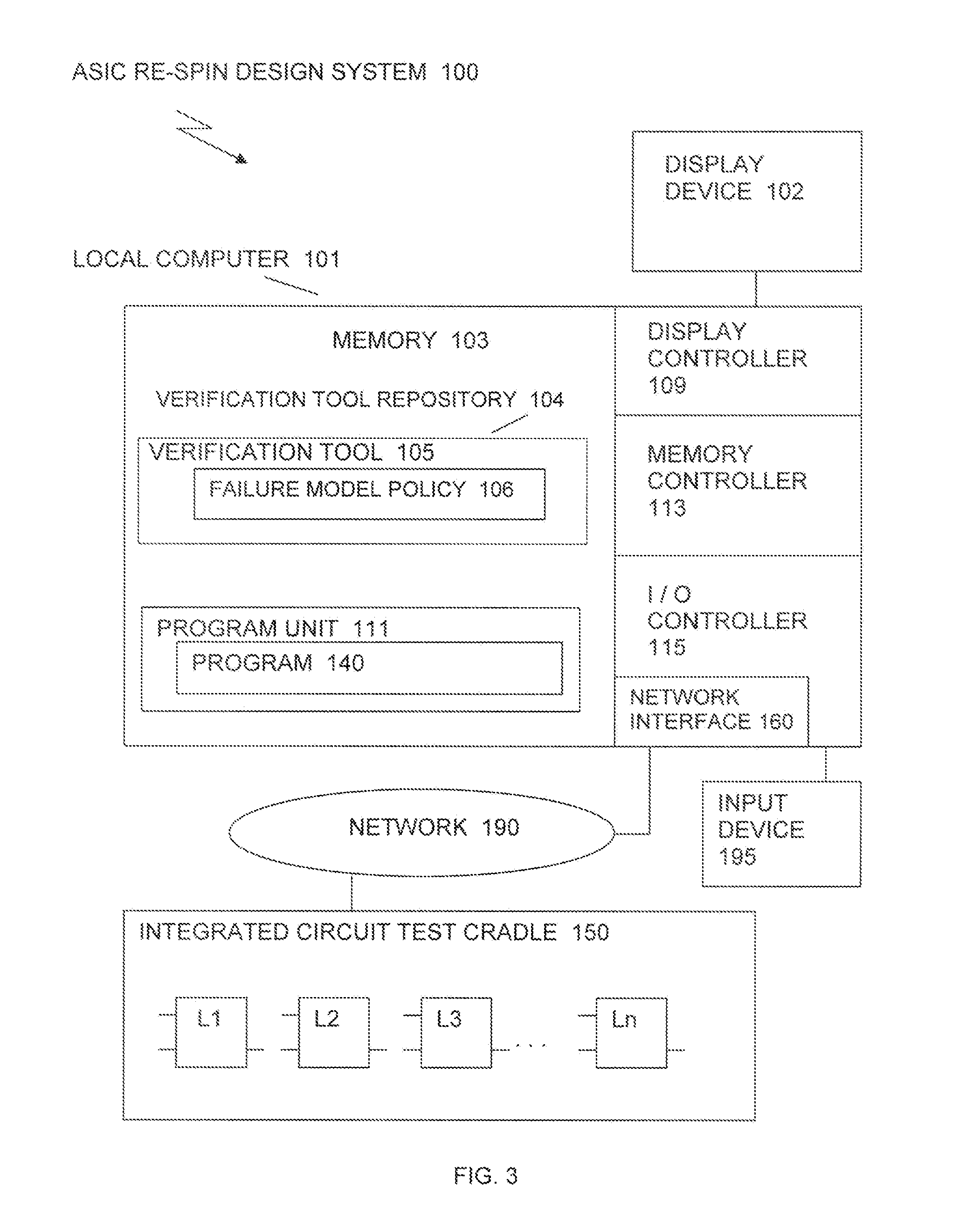
[0010]The exemplary embodiments will be understood by referring to FIGS. 1, 2 and 3. An ASIC re-spin design method 70 is illustrated in FIG. 1. Current project, previous project and working design after logic engineering change order scenarios are illustrated in FIG. 2. Further, the ASIC re-spin design method 70 is implemented in the ASIC re-spin design system 100, illustrated in FIG. 3.

[0011]Referring to FIG. 3, the ASIC re-spin design system 100 (hereafte...


PUM


Abstract

Reducing turn around time of engineering change orders in ASIC re-spin design includes finding, on the fly, all corresponding boundary points of storage gate elements indicated by engineering change orders to be either added, deleted or renamed. Boolean equivalence tools are used between an old spin ASIC design and a new ASIC design netlist, as well as between the new ASIC design netlist and a new re-spin ASIC design to obtain failing boundary storage gate elements and perform one or more of adding, deleting or modifying or renaming all failing boundary storage gate elements, so they pass correspondence tests. Engineering change order scripts are automatically generated to indicate which storage logic gate elements are to be added, deleted or modified and the scripts are applied to the old ASIC design to obtain the new re-spin ASIC design, after which ASIC flow gate level fixes are applied to synthesized storage gate elements.

Description

TECHNICAL FIELD[0001]The present invention relates generally to design, development and manufacturing of integrated circuits (ICs) on semiconductor chips, for use in automated computing systems. More particularly, the present invention relates to reducing the complexity of design and verification tasks in the physical design of new versions of application specific integrated circuit (ASIC) design.BACKGROUND[0002]Known methods and systems for the production of ASIC re-spin in non-hierarchical design is based on several releases, where the first version is designed with limited availability editions (e.g. for production modeling, board testing and debugging purposes) and the successor editions are released based on the gathered feedback from the preliminary production models. It is common to re-design these preliminary productions models from scratch, in terms of time and risk critical, physical design (PD) parameters and re-verify the models from the very beginning. It is desirable t...

Claims


Application Information

Patent Timeline
Patent Type & Authority Applications(United States)
IPC IPC(8): G06F17/50
CPCG06F17/5054G06F30/34
Inventor FEDEROVSKY, DOVKAMSHITSKY, DMITRYVAISBAND, INNAYEGER, BOAZ
Owner GLOBALFOUNDRIES INC
Learn More