Vibrating piece manufacturing method and vibrator manufacturing method

a manufacturing method and vibrator technology, applied in the direction of conductive pattern formation, generator/motor, device material selection, etc., can solve the problems of limited control range and small control of vibration frequency obtained by controlling weight, so as to reduce flexural rigidity of arms, increase the control range of vibration frequency, and reduce the thickness

Inactive Publication Date: 2009-07-16
SEIKO EPSON CORP
View PDF4 Cites 17 Cited by
  • Summary
  • Abstract
  • Description
  • Claims
  • Application Information

AI Technical Summary

Benefits of technology

[0005]An advantage of the invention is to expand the control range of vibration frequency.
[0006]A vibrating piece manufacturing method according to a first aspect of the invention includes: (a) preparing a supporting body having first and second surfaces, the first and second surfaces defining a thickness while being directed toward opposite directions, the supporting body including a base and a plurality of arms, the arms extending side-by-side in a direction orthogonal to a direction of the thickness from the base, a lower electrode film being disposed on the first surface of each of the arms, a piezoelectric film being disposed on the lower electrode films, at least one upper electrode film being disposed on the piezoelectric film, at least a part of the second surface of each of the arms being an exposed area; and (b) etching the exposed area of the second surface so as to reduce the thickness to reduce flexural rigidity of the arms with respect to the thickness direction.
[0007]By adopting this method, the thickness of the arms is controlled so that the flexural rigidity is controlled. As a result, the vibration frequency is controlled. Since the amount of control of the frequency obtained by controlling the thickness of the arms is larger than that obtained by controlling the weight, the control range of the vibration frequency is expanded.
[0008]In the vibrating piece manufacturing method according to the first aspect of the invention, before step (b), a weight metal film is preferably formed on the second surface of each of the arms, and in step (b), a surface of the weight metal film is preferably also etched.
[0009]A vibrating piece manufacturing method according to a second aspect of the invention includes: (a) preparing a supporting body having first and second surfaces, the first and second surfaces defining a thickness while being directed toward opposite directions, the supporting body including a base and a plurality of arms, the arms extending side-by-side in a direction orthogonal to a direction of the thickness from the base, a lower electrode film being disposed on the first surface of each of the arms, a piezoelectric film being disposed on the lower electrode films, at least one upper electrode film being disposed on the piezoelectric film, at least a part of the second surface of each of the arms being an exposed area; and (b) forming a reinforcing metal area in the exposed area of the second surface so as to increase flexural rigidity of the arms with respect to the thickness direction.

Problems solved by technology

However, the amount of control of the vibration frequency obtained by controlling the weight is small.
Therefore, the control range is limited.

Method used


Image

  • Vibrating piece manufacturing method and vibrator manufacturing method
  • Vibrating piece manufacturing method and vibrator manufacturing method
  • Vibrating piece manufacturing method and vibrator manufacturing method

Examples


first embodiment

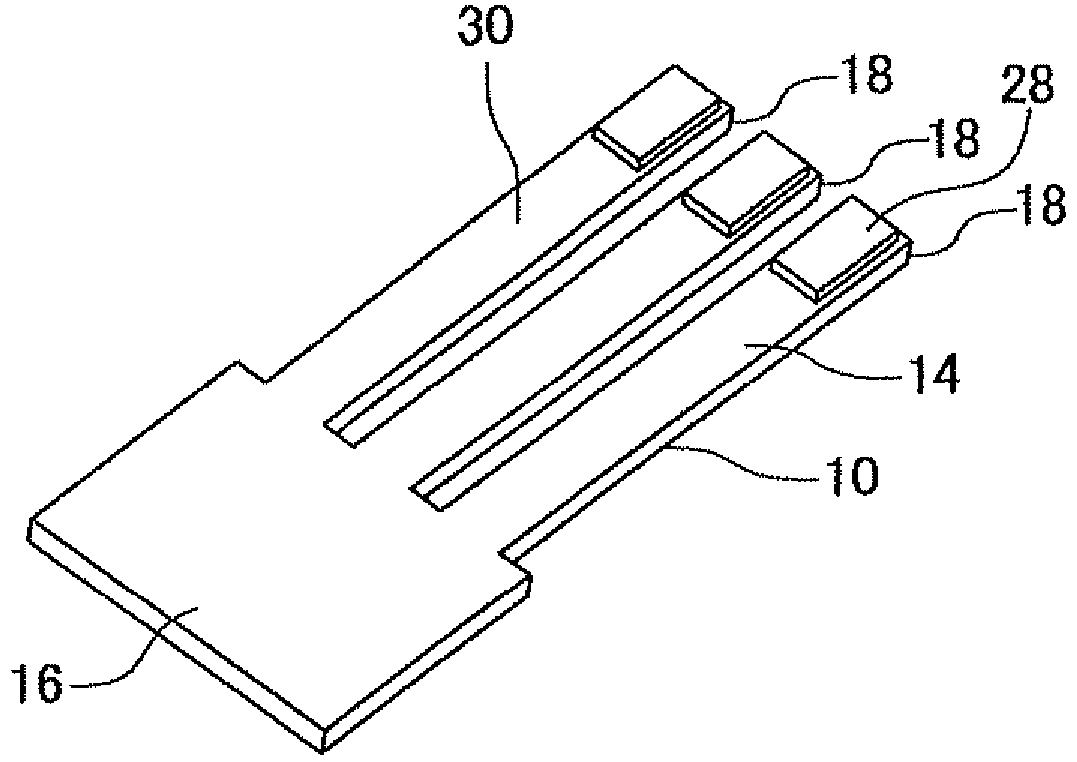
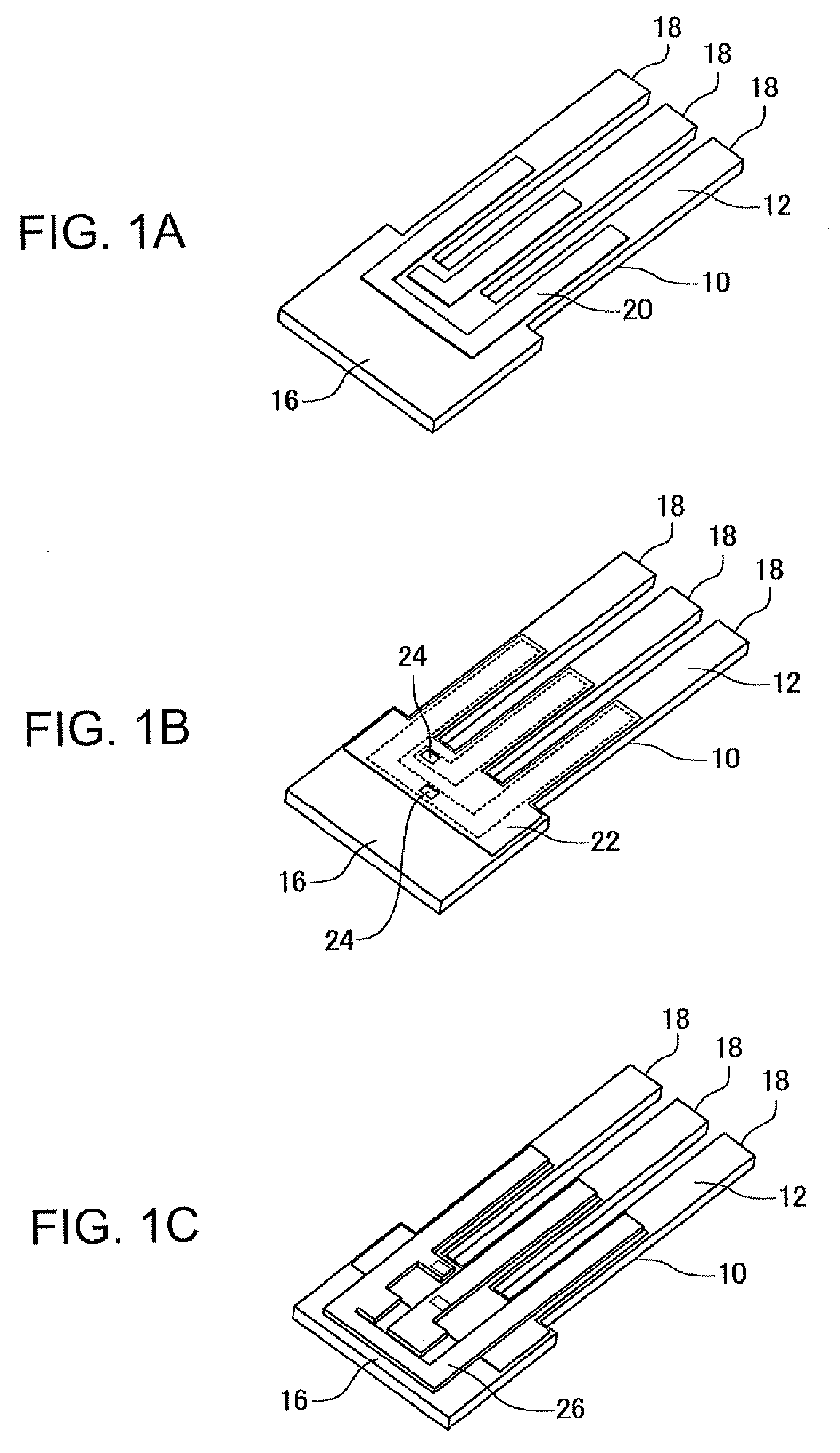
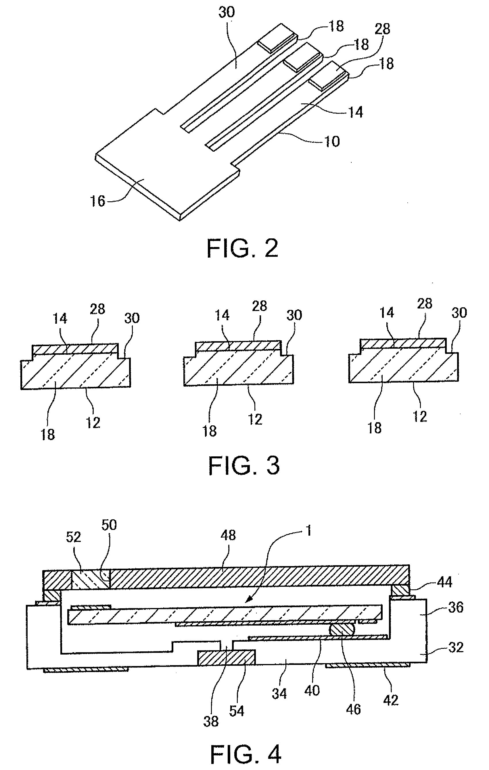
[0025]FIGS. 1A to 3 are drawings showing a vibrating piece manufacturing method according to a first embodiment of the invention. In this embodiment, a supporting body 10 is prepared. The supporting body 10 may be made of a piezoelectric material (for example, a Z-cut plate, an AT-cut plate, an X-cut plate) such as quartz or may be made of silicon. The supporting body 10 has first and second surfaces 12 and 14 that define the thickness while being directed toward opposite directions. The supporting body 10 includes a base 16 and multiple (an odd number of) arms 18 extending side-by-side from the base 16 in a direction orthogonal to the thickness direction. While the width of an arm 18 located in the middle of the arms 18 that are lining up may be larger than or equal to the width of the remaining arms 18, all the arms 18 have an identical thickness. This shape is obtained by etching (at least one of wet etching and dry etching) a plate material.

[0026]As shown FIG. 1A, a lower electr...

second embodiment

[0055]FIG. 8 is a drawing showing a vibrating piece manufacturing method according to a second embodiment of the invention. A supporting body 310 prepared in this embodiment is the same as the supporting body 10 prepared in the first embodiment except that no weight metal films are formed on a second surface 314. In this case, all of the second surface 314 of each of arms 318 may be an exposed area 330 where the material of the supporting body 310 is exposed.

[0056]In this embodiment, a reinforcing metal film 356 is formed on each of the exposed areas 330 of the second surfaces 314. For example, by depositing SiO2, Au, Cr, Al or the like, the reinforcing films 356 are formed. The reinforcing films 356 make the multiple arms 318 less flexible in the thickness direction. That is, a portion including an arm 318 and a reinforcing metal film 356 is larger in thickness than the original arm 318. As a result, the rigidity is increased so that the frequency is increased. By adopting this emb...


PUM

PropertyMeasurementUnit
thicknessaaaaaaaaaa
flexural rigidityaaaaaaaaaa
weightaaaaaaaaaa

Abstract

A vibrating piece manufacturing method includes: (a) preparing a supporting body having first and second surfaces, the first and second surfaces defining a thickness while being directed toward opposite directions, the supporting body including a base and a plurality of arms, the arms extending side-by-side in a direction orthogonal to a direction of the thickness from the base, a lower electrode film being disposed on the first surface of each of the arms, a piezoelectric film being disposed on the lower electrode films, at least one upper electrode film being disposed on the piezoelectric film, at least a part of the second surface of each of the arms being an exposed area; and (b) etching the exposed area of the second surface so as to reduce the thickness to reduce flexural rigidity of the arms with respect to the thickness direction.

Description

BACKGROUND[0001]1. Technical Field[0002]The present invention relates to a vibrating piece manufacturing method and a vibrator manufacturing method.[0003]2. Related Art[0004]There has been known a technology for, in order to control the vibration frequency of a vibrating piece for use in an oscillator or the like, eliminating a part of a metal film of a vibrating arm using a laser beam (JP-A-2002-252546). Specifically, by eliminating a part of a metal film, the weight of the metal film is reduced so that the vibration frequency is controlled. However, the amount of control of the vibration frequency obtained by controlling the weight is small. Therefore, the control range is limited.SUMMARY[0005]An advantage of the invention is to expand the control range of vibration frequency.[0006]A vibrating piece manufacturing method according to a first aspect of the invention includes: (a) preparing a supporting body having first and second surfaces, the first and second surfaces defining a t...

Claims


Application Information

Patent Timeline
Patent Type & Authority Applications(United States)
IPC IPC(8): H01L41/22H01L41/09H01L41/18H01L41/23H01L41/253H03H3/02H03H3/04H03H9/02H03H9/215
CPCH03H3/04H03H9/1021H03H9/21Y10T29/49155Y10T29/49574Y10T29/42Y10T29/49005
Inventor YAMAZAKI, TAKASHIFUNASAKA, TSUKASAFUNAKAWA, TAKEOFURUHATA, MAKOTO
Owner SEIKO EPSON CORP
Why Eureka
Try Eureka