Exhaust gas purifying apparatus

a technology of exhaust gas purification and purification chamber, which is applied in the direction of exhaust treatment electric control, machines/engines, separation processes, etc., can solve the problems of increasing the amount, the catalyst placed in the exhaust gas purification apparatus does not adequately reach the optimum temperature, and it is difficult to use a usual ceramic support. , to achieve the effect of efficiently eliminating specified materials, increasing the size of the exhaust gas purifying apparatus, and rapid increase of the catalyst temperatur

Inactive Publication Date: 2009-07-23
DENSO CORP
View PDF0 Cites 21 Cited by
  • Summary
  • Abstract
  • Description
  • Claims
  • Application Information

AI Technical Summary

Benefits of technology

[0010]When observed from the flowing direction of the exhaust gas in the exhaust gas passage formed in the exhaust gas pipe, the throttle unit is placed on at least one of the upstream side and the downstream side thereof. The throttle unit locally introduces the exhaust gas into a part of the catalyst placed in the catalyst unit when the temperature of the catalyst is lower than its activation temperature. That structure allows the exhaust gas emitted from an internal combustion engine to be introduced into the part of the catalyst when the temperature of the catalyst is low, namely, in the early period of starting the internal combustion engine. This allows the temperature of the part of the catalyst to locally and rapidly rise, through which the exhaust gas is concentrated in flow to the part of the catalyst such as the central part or the outer peripheral part of the catalyst. On th

Problems solved by technology

Internal combustion engines such as diesel engines and gasoline engines include a problem of increasing the amount of specified materials such as hydro carbon (HC), carbon monoxide (CO), and nitrogen oxide (NOx) contained in an exhaust gas emitted from such an internal combustion engine mounted to a vehicle when the temperature of catalyst placed in an exhaust gas purifying apparatus mounted to the vehicle is low, for example, during early period of starting the internal combustion engine.
For this reason, the catalyst placed in the exhaust gas purifying apparatus does not adequately re

Method used


Image

  • Exhaust gas purifying apparatus
  • Exhaust gas purifying apparatus
  • Exhaust gas purifying apparatus

Examples


first embodiment

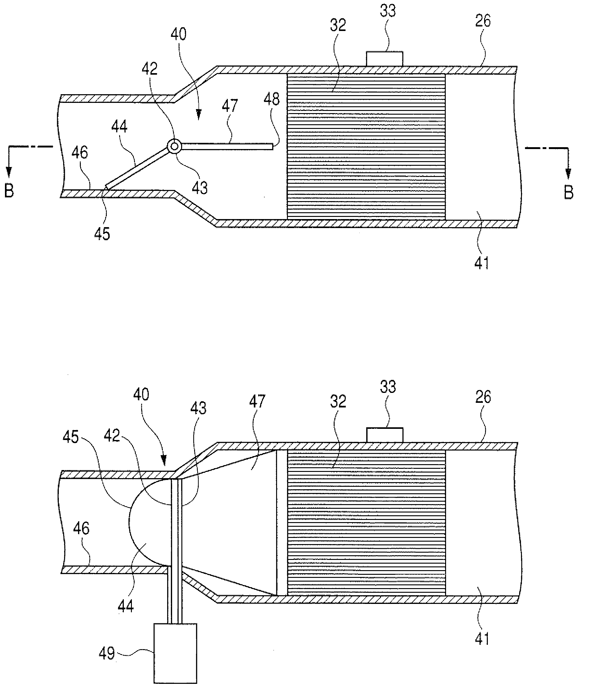
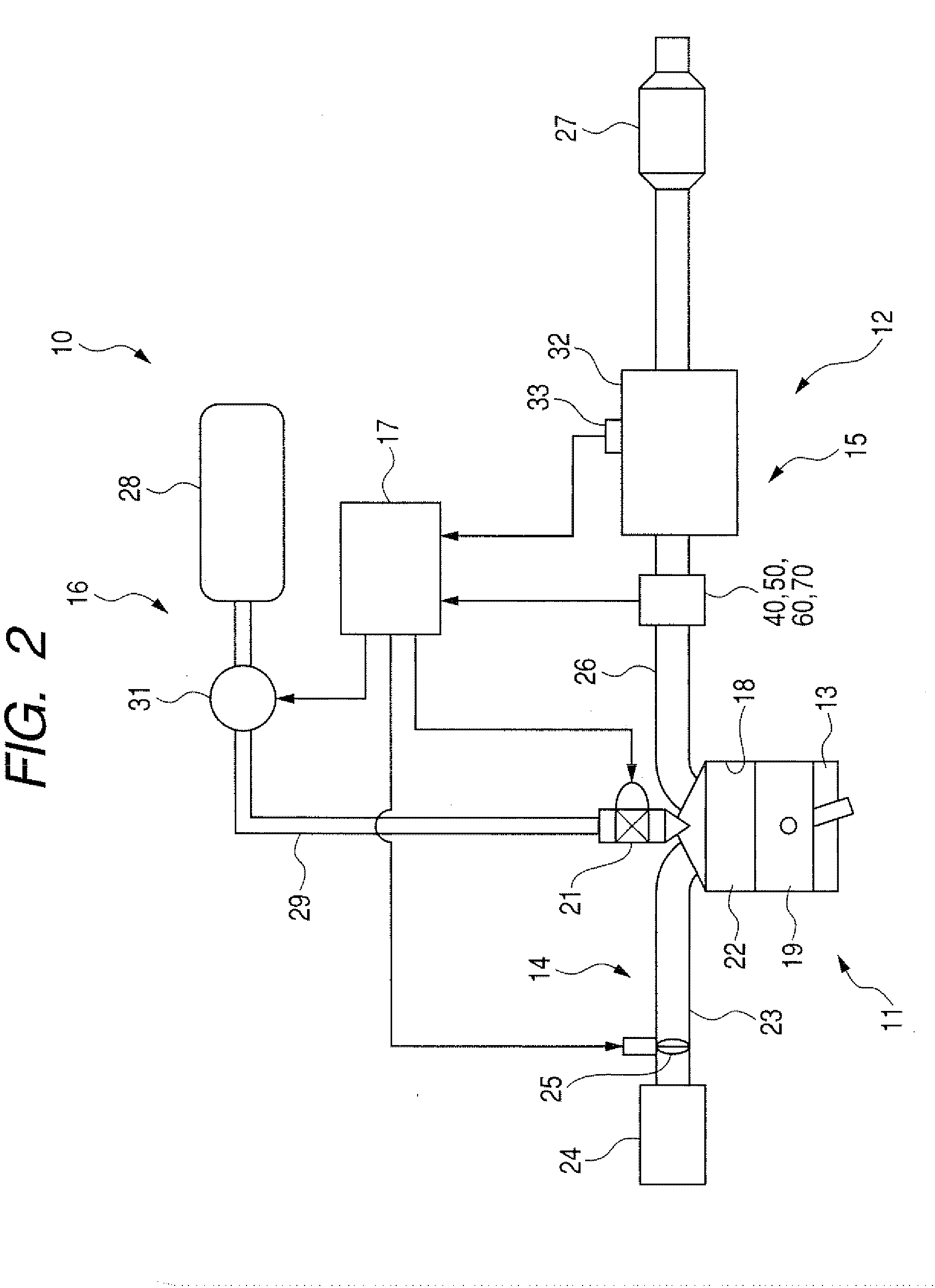
[0026]FIG. 2 shows a schematic diagram of an gasoline engine system as an internal combustion engine system equipped with an exhaust gas purifying apparatus according to the first embodiment of the present invention. As shown in FIG. 2, the engine system 10 has a gasoline engine 11 and an exhaust gas purifying apparatus 12. The gasoline engine 11 is comprised of an engine main system 13, an intake air system 14, an exhaust gas system 15, a gasoline supply system 16, and a control unit 17 (or an electronic control unit (ECU)).

[0027]The engine main system 13 has pistons which are located in cylinders. Each piston 13 performs reciprocating motion in the corresponding cylinder. Each cylinder 18 is equipped with an injector 21 to inject a fuel. The gasoline engine 18 uses gasoline as fuel. It is possible to use liquefied petroleum gas (LPG), liquefied natural gas (LNG), and alcohol such as ethanol instead of gasoline as fuel.

[0028]It is also possible for the engine system 10 to incorpora...

second embodiment

[0087]A description will be given of the exhaust gas purifying apparatus according to the second embodiment of the present invention with reference to FIG. 6.

[0088]FIG. 6 is a schematic cross section of a part of the exhaust gas purifying apparatus according to the second embodiment of the present invention. As shown in FIG. 6, the exhaust gas purifying apparatus 12 of the second embodiment has a throttle unit 50 instead of the throttle unit 40 according to the first embodiment. The throttle unit 50 of the second embodiment has a pair of the throttle valve members 51 and a pair of valve drive units 52. Each throttle valve member 51 is a plate shape. One end of each throttle valve member 51 is rotatably fixed to the inner wall of the exhaust gas pipe 26. That is, each exhaust gas pipe 26 rotates around a rotary shaft 53. As shown in FIG. 6, each throttle valve member 51 has a movable end part 54 which is extended toward the three way catalyst unit 32 side. According to the rotation o...

third embodiment

[0098]A description will be given of the exhaust gas purifying apparatus according to the third embodiment of the present invention with reference to FIG. 7.

[0099]FIG. 7 is a schematic cross section of a part of the exhaust gas purifying apparatus according to the third embodiment of the present invention. As shown in FIG. 7, the exhaust gas purifying apparatus of the third embodiment has a throttle unit 60 instead of the throttle units 40 and 50 of the first and second embodiments.

[0100]The throttle unit 60 has a pair of throttle valve members 61. Each throttle valve member 61 has a bimetal 62. The bimetal 62 drives the corresponding throttle valve member 61. The bimetal 62 is deformed according to the temperature change of the exhaust gas. That is, the deformation of the bimetal 62 drives a movable end part 64 of the throttle valve member 61 from the central part toward the outer part of the three way catalyst unit 32. That is, the bimetal 62 serves as a valve drive member which w...


PUM


Abstract

A throttle unit placed in an exhaust gas passage controls an opening-ratio of each of first and second valve members to control a gas-flow sectional area of the exhaust gas passage. When the temperature of a three-way catalyst is low, the throttle unit introduces the exhaust gas flow into a part of an outer-periphery of the three-way catalyst. This control can rapidly increase the temperature of the three-way catalyst from an early period of starting an internal combustion engine within a short period of time. The throttle unit increases the gas-flow sectional area of the exhaust gas passage according to increasing the temperature of the three-way catalyst. When the three-way catalyst reaches its activation temperature, the throttle unit instructs the first and second valve members to fully open. This decreases a pressure loss of the exhaust gas because the exhaust gas is supplied into the entire of the three-way catalyst.

Description

CROSS-REFERENCE TO RELATED APPLICATION[0001]This application is related to and claims priority from Japanese Patent Application No. 2008-8305 filed on Jan. 17, 2008, the contents of which are hereby incorporated by reference.BACKGROUND OF THE INVENTION[0002]1. Field of the Invention[0003]The present invention relates to an exhaust gas purifying apparatus using a catalyst such as a three way catalyst capable of purifying an exhaust gas emitted from an internal combustion engine such as a diesel engine under a low temperature of the catalyst in the early period of starting the internal combustion engine.[0004]2. Description of the Related Art[0005]Internal combustion engines such as diesel engines and gasoline engines include a problem of increasing the amount of specified materials such as hydro carbon (HC), carbon monoxide (CO), and nitrogen oxide (NOx) contained in an exhaust gas emitted from such an internal combustion engine mounted to a vehicle when the temperature of catalyst p...

Claims


Application Information

Patent Timeline
IPC IPC(8): F01N9/00F01N13/08
CPCB01D53/9454B01D2258/012B01D2258/014F01N3/0842F01N3/2006F01N3/2013F01N13/0097F01N3/2066F01N3/2892F01N2560/06Y02T10/26Y02T10/22F01N3/2033Y02T10/12
Inventor ARAKAWA, MIYAONISHIJIMA, YOSHIAKIKUROYANAGI, MASATOSHI
Owner DENSO CORP
Why Eureka
Try Eureka