Temperature control device and processing apparatus using the same

a technology of temperature control device and processing apparatus, which is applied in mechanical pressure/force control, lighting and heating apparatus, instruments, etc., can solve the problems of difficult to quickly adjust the current temperature to the target temperature, poor response characteristic, and overshoot and hunting, so as to reduce the risk of overshoot and hunting, minimize the effect of dynamic error and low cos

Inactive Publication Date: 2009-07-23
TOKYO ELECTRON LTD
View PDF3 Cites 75 Cited by
  • Summary
  • Abstract
  • Description
  • Claims
  • Application Information

AI Technical Summary

Benefits of technology

[0017]In accordance with the present invention, since the temperature control of the control target is carried out by modelizing the control target and the external factors by using the ILQ control method, the optimal parameters can be determined uniquely by using the inverse problem of the optimal regulator, so that error and input can be minimized, and response can also be specified. Accordingly, the follow-up property to the target value is excellent and the dynamic error can be minimized. Moreover, unlike the PID control, since no overshoot occurs and control amount can be optimized in consideration of the capacity of the power supply, energy efficiency is raised in comparison with the case of the PID control. Further the ILQ control has a good robustness, and control efficiency can be maintained even in case that the control target model varies within a certain range.
[0018]Further, by dividing the wall portion of t...

Problems solved by technology

When performing the temperature control by the PID control, however, problems of overshoot and hunting occur if sensitivity to the difference is increased.
Accordingly, it also takes setting time so that it is difficult to adjust the current temperature to the target temperature promptly.
Moreover, since the control is performed based on the difference between the target temperature and th...

Method used


Image

  • Temperature control device and processing apparatus using the same
  • Temperature control device and processing apparatus using the same
  • Temperature control device and processing apparatus using the same

Examples


Embodiment Construction

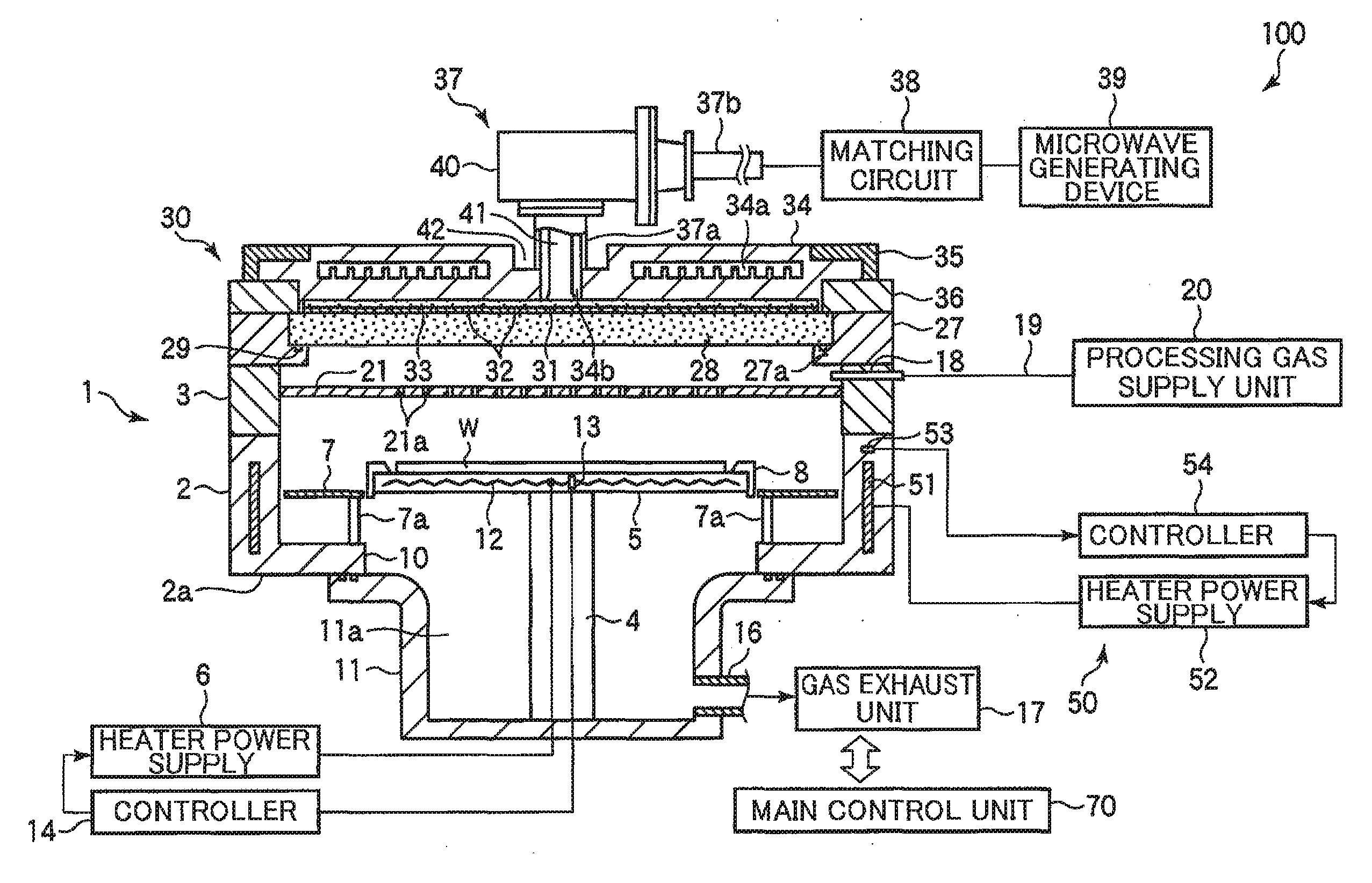
[0030]Hereinafter, embodiments of the present invention will be described in detail with reference to the accompanying drawings. Here, description will provided for an example case of applying a temperature control device of the present invention to a chamber wall (a housing unit) of a microwave plasma processing apparatus.

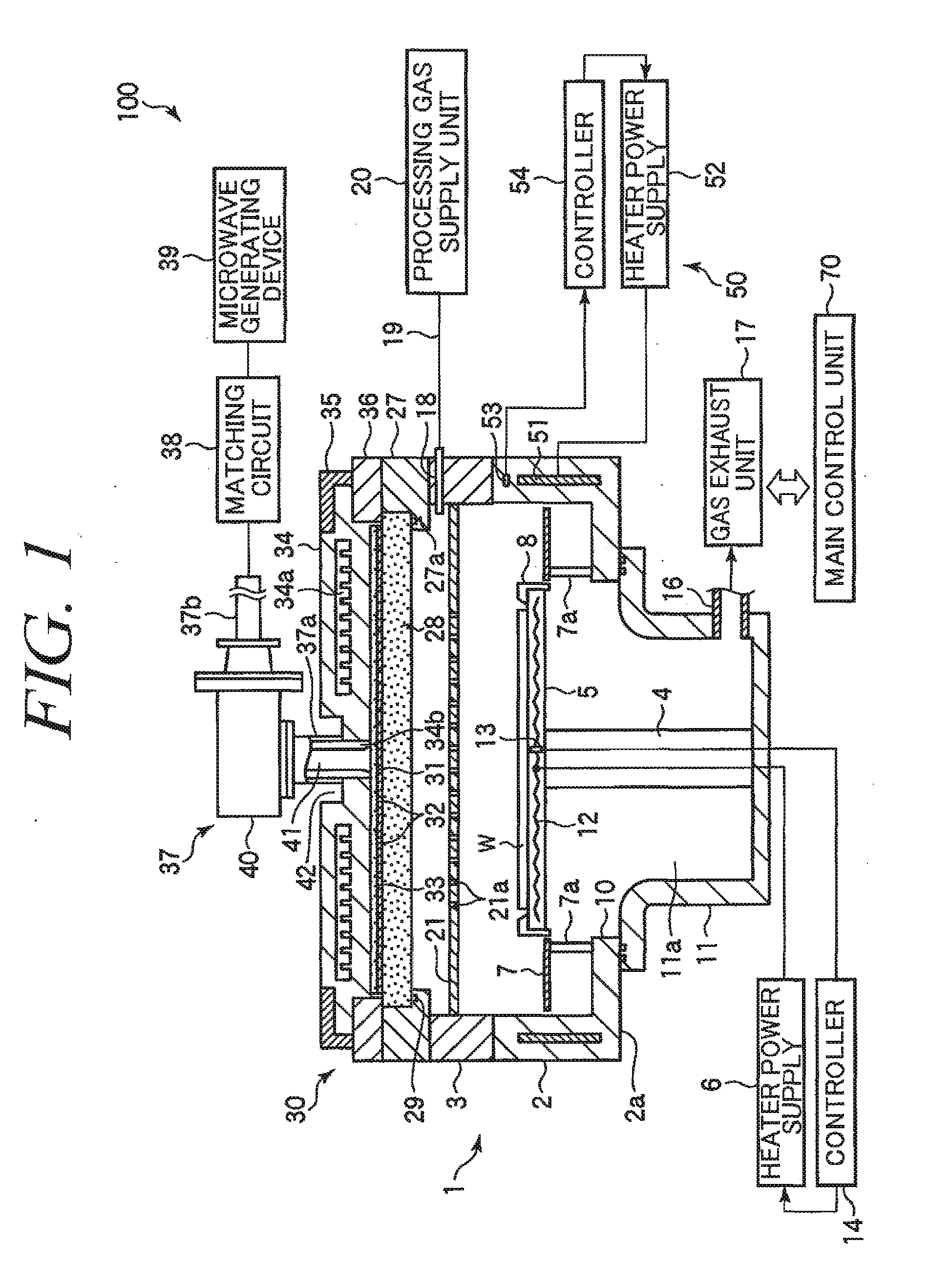
[0031]FIG. 1 is a schematic cross sectional view showing a microwave plasma processing apparatus to which a temperature control device in accordance with an embodiment of the present invention is applied. The microwave plasma processing apparatus 100 is configured as a plasma film forming apparatus which generates microwave plasma having high density and low electron temperature by introducing microwave into a processing chamber from a planar antenna having a plurality of slots, e.g., a RLSA (Radial Line Slot Antenna), and performs a film forming process by using the microwave plasma.

[0032]The plasma processing apparatus 100 includes an approximately cylindrical c...


PUM


Abstract

Provided are a temperature control device capable of performing a temperature control of, e.g., a chamber wall of a processing apparatus with a high precision; and a processing apparatus using the same. The temperature control device 50 includes a plurality of heater units 51 for heating each of a multiplicity of zones 55 into which a wall portion of a housing 2 of a chamber 1 is divided; a multiplicity of heater power supplies 52 for supplying power to each of the plurality of heater units 51; a number of thermocouples 53 for measuring the temperature of each of the multiplicity of zones 55; and a plurality of controllers 54 for controlling a corresponding power supply unit by an ILQ control based on a signal from each temperature sensor to set a temperature of a corresponding zone to a preset target temperature.

Description

FIELD OF THE INVENTION[0001]The present invention relates to a temperature control device for use in a processing apparatus for performing a process accompanied by heat such as a plasma process on a target object such as a semiconductor wafer or the like; and the processing apparatus using the temperature control device.BACKGROUND OF THE INVENTION[0002]Conventionally, for example, in a manufacturing process of a semiconductor device, various processes such as etching, ashing, film formation, and the like are performed on a semiconductor wafer (hereinafter, simply referred to as a “wafer”) which is a target object to be processed. These processes are performed by mounting the wafer on a mounting table in a chamber and controlling the temperatures of the mounting table, a chamber housing, and so forth. Especially, in case of a film forming process, since a control of deposition on a housing wall portion constituting the chamber is critical, a highly precise temperature control is requ...

Claims


Application Information

Patent Timeline
IPC IPC(8): B05C9/14
CPCH01L21/67248H01L21/67098E05B17/20E05D3/02E05D7/00
Inventor TIAN, CAIZHONGISHIBASHI, KIYOTAKANOZAWA, TOSHIHISA
Owner TOKYO ELECTRON LTD
Why Eureka
Try Eureka