Supercharge Your Innovation With Domain-Expert AI Agents!

Laser assembly with electronic masking system

a laser assembly and masking technology, applied in the field of laser assembly, can solve the problems of not being, or being easily, modifiable, and taking a long time to produce, and achieve the effect of high laser beam quality

Inactive Publication Date: 2009-07-23
LEISTER TECHNOLOGIES
View PDF6 Cites 2 Cited by
  • Summary
  • Abstract
  • Description
  • Claims
  • Application Information

AI Technical Summary

Benefits of technology

The invention is a laser assembly for processing or joining work pieces using electromagnetic radiation. It includes a laser source with a high-quality beam and an electronic masking system with a phase modulation array. The masking system can create sharp images on the work pieces with a high degree of focus. The laser assembly has a common pixel size larger than four micrometers and a laser source with a high beam quality. It can be used for transmission welding of plastic materials and can also be used for scanning or contour welding. The position sensitivity of the pattern imaged on the work pieces is determined by the beam quality and the geometry of the individual liquid crystal cells. The invention provides a flexible and efficient tool for processing or joining work pieces.

Problems solved by technology

On the one hand, this may be accomplished with special optical systems or masks that are tailored to the specific task but take a long time to produce and are not, or not easily, modifiable in most cases.

Method used


Image

  • Laser assembly with electronic masking system
  • Laser assembly with electronic masking system

Examples


Embodiment Construction

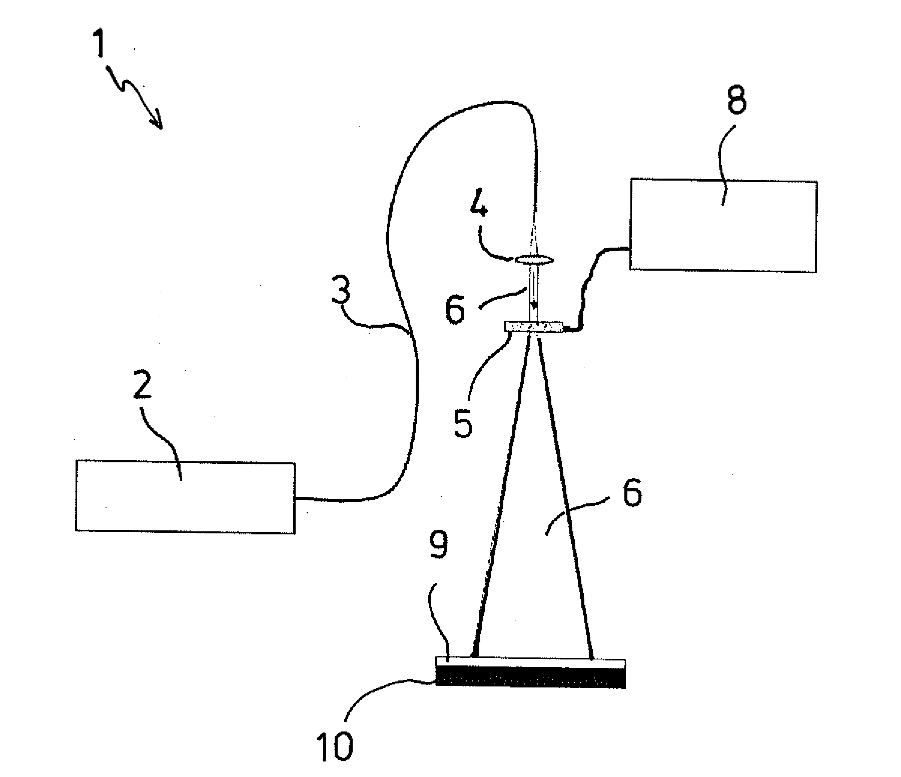
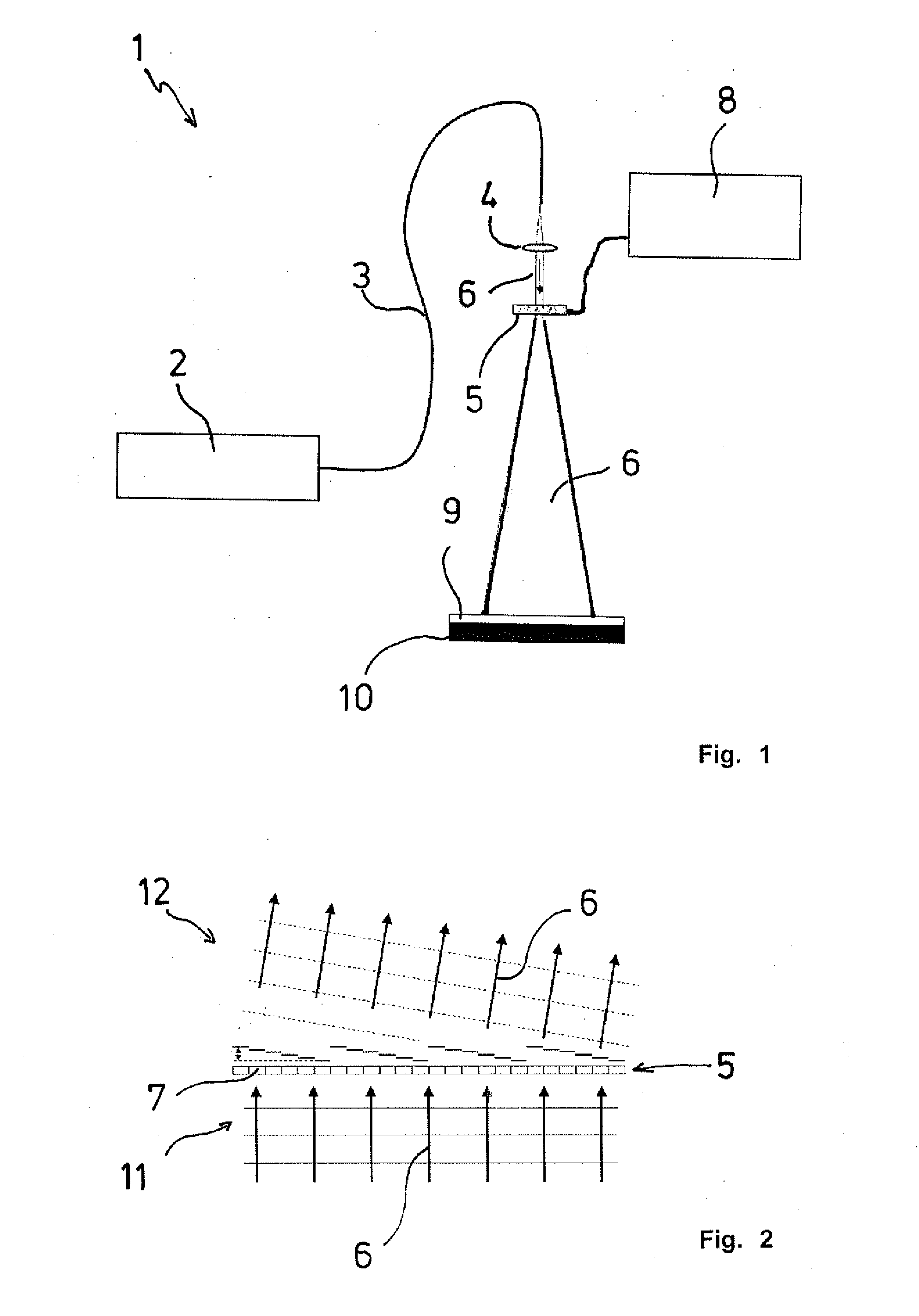
[0025]FIG. 1 shows the laser assembly 1 according to the invention, comprising a fiber laser 2, a fiber-optic conductor 3 leading to a processing head (not shown) in which an optical lens 4 for forming the beam and a phase modulation array 5 for the phase modulation of the radiation of a laser beam 6 are located. The laser beam 6 exiting from the optic conductor 3 is bundled by the lens 4 and projected onto the liquid crystal cells 7, shown in FIG. 2, of the phase modulation array 5.

[0026]The liquid crystal cells 7 of the phase modulation array 5 can be controlled individually and independent of each other by means of an electronic control system 8, and modulate the phases of the impinging laser beam 6 at certain locations in a pre-selected manner as desired in an identical and / or different way. In the embodiment shown here, the phase modulation array 5 is operated in transmission so that the laser beam 6 passes the liquid crystal cells 7, which generates a certain beam pattern that...


PUM

PropertyMeasurementUnit
sizeaaaaaaaaaa
sizeaaaaaaaaaa
wavelengthaaaaaaaaaa

Abstract

The invention concerns a laser assembly for processing or joining work pieces by means of electromagnetic radiation, with a laser source that emits a laser beam, and an electronic masking system for the work pieces that succeeds the laser source. The masking system images the passing laser beam on the work pieces in a pattern that is randomly selectable. As masking system, a phase modulation array with preferably a common pixel size >4 μm is used, and also a laser source with a high beam quality of the laser beam that together permit the sharp imaging of patterns with a line width <2 mm on the work pieces.

Description

TECHNICAL FIELD OF THE INVENTION[0001]The invention concerns a laser assembly for processing or joining work pieces by means of electromagnetic radiation, with a laser source that emits a laser beam, and an electronic masking system for the work pieces that succeeds the laser source, with the masking system imaging the passing laser beam on the work pieces in a pattern that is randomly selectable.DESCRIPTION OF THE RELATED ART[0002]When processing or joining work pieces with electromagnetic radiation, specifically with a laser beam, the size and the shape of the beam profile focused on the work pieces play an important role. During laser processing, correct selection of the power density distribution within the generated focal spot is also important. With laser beam welding, for example with transmission welding of plastic materials, it is often necessary to generate heat distribution patterns or welding seams of many different shapes.[0003]As a rule, laser sources have a round beam...

Claims


Application Information

Patent Timeline
Patent Type & Authority Applications(United States)
IPC IPC(8): B23K26/00
CPCB23K26/0656B29C65/16B29C65/1654B29C65/1687G02F2203/12B29C66/1122B29C66/43G02F1/216G02F2001/291B29C65/1696B23K26/066G02F1/291
Inventor GUBLER, ULRICHZURBUCHEN, RETO
Owner LEISTER TECHNOLOGIES
Features
  • R&D
  • Intellectual Property
  • Life Sciences
  • Materials
  • Tech Scout
  • Unparalleled Data Quality
  • Higher Quality Content
  • 60% Fewer Hallucinations
Learn More