Polymer blends and their use in organic light emitting devices

a technology of organic light emitting devices and polymer blends, which is applied in the manufacture of final products, discharge tubes/lamp details, synthetic resin layered products, etc., can solve the problems of poor lifetime, inability to manufacture additional interlayers, and inability to meet the requirements of mass production,

Inactive Publication Date: 2009-07-23
MERCK PATENT GMBH
View PDF13 Cites 50 Cited by
  • Summary
  • Abstract
  • Description
  • Claims
  • Application Information

AI Technical Summary

Benefits of technology

[0350]FIG. 8 clearly shows that using a polymer blend according to the invention as emissive layer in an interlayer device can still significantly improve the lifetime, in this case from 304 hrs to 470 hrs.

Problems solved by technology

Single layer PLEDs, where the hole transport, electron transport and emissive layer are combined into one layer, have the advantage of simple processing, however, they do often show poor lifetime.
However, the additional interlayer is undesired in mass production.
Also, since its processing is not easy and well controllable, the reliability of the performance of a PLED comprising such an interlayer is usually not sufficient for mass production.
In contrast, a blend consisting of polymers having a large bandgap offset is usually considered to be advantageous only for use in photovoltaic cells, but disadvantageous for use in PLEDs.
However, no further enabling technical disclosure is provided in this direction.
In fact, no such blend system with long lifetime has been reported so far.

Method used


Image

  • Polymer blends and their use in organic light emitting devices
  • Polymer blends and their use in organic light emitting devices
  • Polymer blends and their use in organic light emitting devices

Examples


example 1

Polymers

[0320]The following polymers are synthesized by Suzuki coupling as disclosed in WO03 / 048225.

[0321]Polymer1 is the copolymer of following monomers:

[0322]Polymer2a is the copolymer of following monomers:

[0323]Polymer2b is the copolymer of following monomers:

[0324]Polymer2c is the copolymer of following monomers:

[0325]Polymer2d is the copolymer of following monomers:

example 2

Cyclovoltammetry Measurement on the Polymers

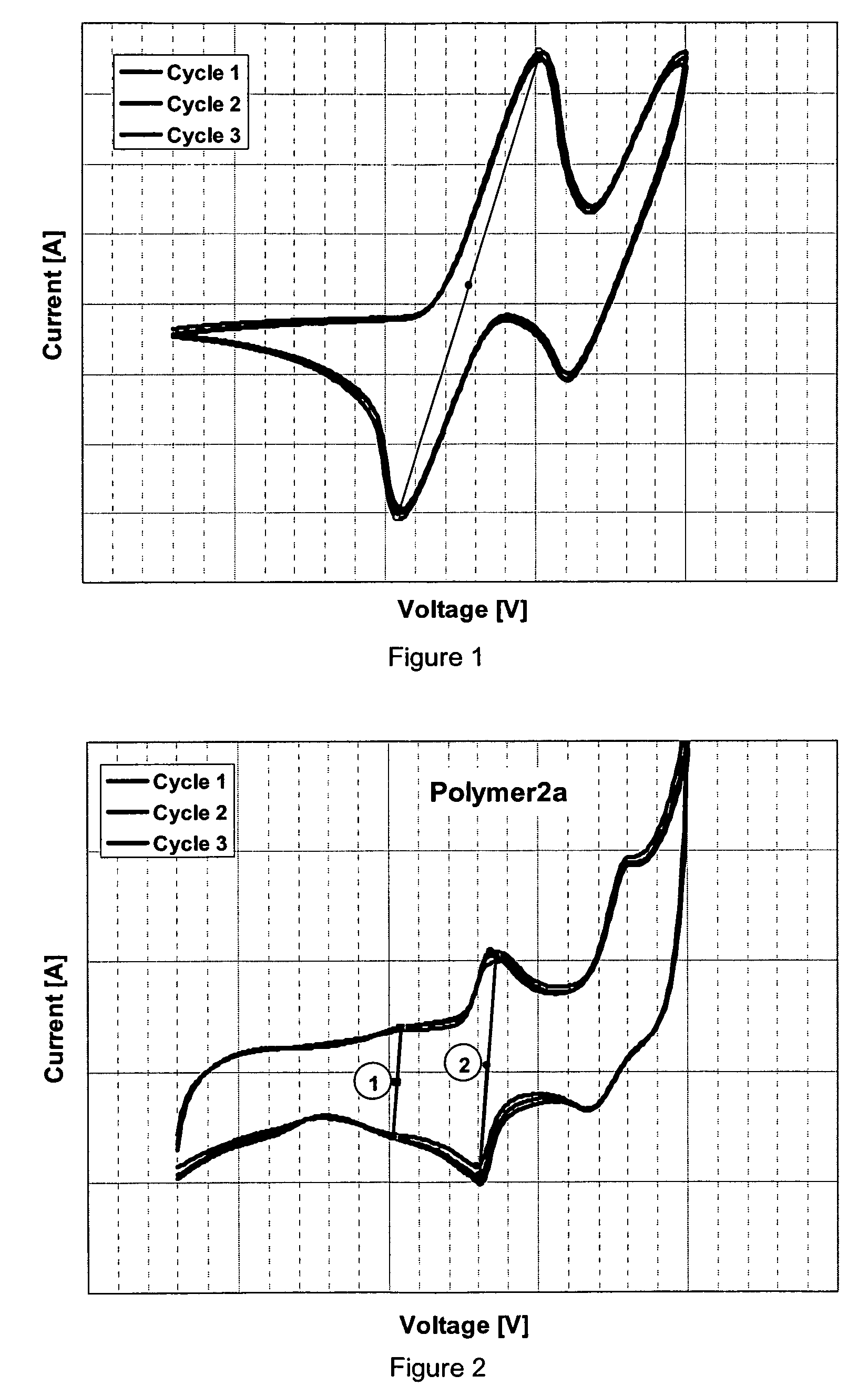
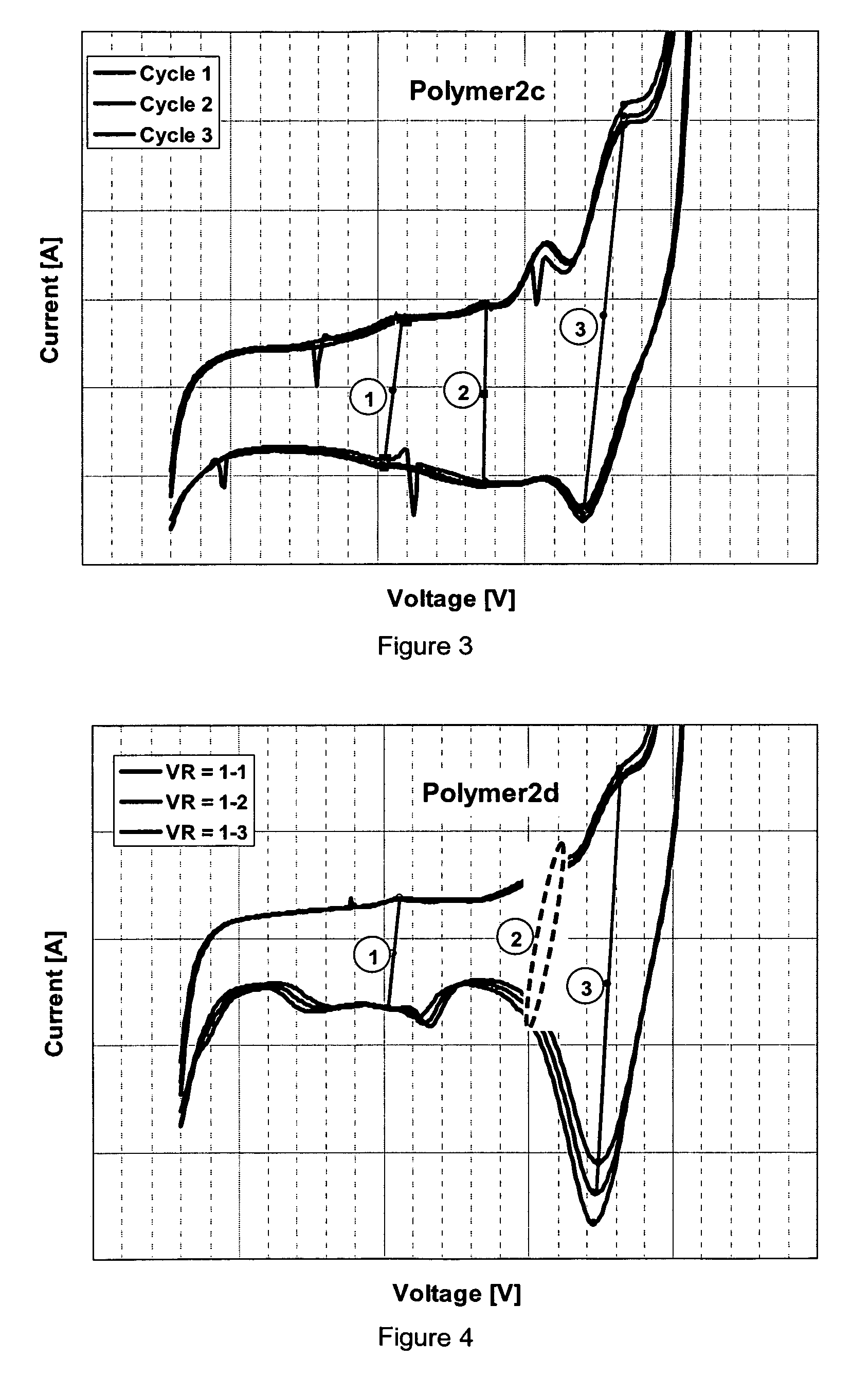
[0326]The HOMO levels of the above polymers are measured by cyclovoltammetry (CV). The CV measurements are conducted in dichlormethane solution using tetrabutylammonium chloride as conducting salt, Ag / AgCl / KCl (3 mol / l) as reference electrode, Au as working electrode and Pt as counter electrode. FIG. 1, FIG. 2, FIG. 3 and FIG. 4 are the CV curves for poylmer1, polymer2a, polymer2c and polymer2d. 3 cycles were measured for every polymer. The HOMO levels were calculated by the average voltage of the local maximum peak in oxidation-curve and corresponding local minimum peak reduction-curve. Care should be taken to find the correct local minima and maxima, for example change the axis case to find all peaks. The results are summarised in Table 1, with the alignments of the different function groups to the corresponding peaks.

[0327]For polymer1, polymer2a and polymer2c, all peaks are very clearly spotted. All there cycles give essentially the sa...

example 3

Quantum Simulation on Energy Levels of the Polymers

[0328]As mentioned before, the applicants established a very reliable quantum simulation method to determine the energy levels of organic materials. The HOMO and LUMO levels of individual units are calculated by Gaussian 03W using the DFT method. In the calculation, the trimer M2-M1-M2 is taken as hole transport unit in polymer1; M4-M3-M4 as electron transport unit and M4-M5-M4 as both exciton formation and emissive unit in polymer2a; M6-M3-M6 as electron transport unit and M6-M5-M6 as both exciton formation and emissive unit in polymer2b; M6-M3-M6 as electron transport unit, M6-M5-M6 as exciton formation unit and M6-M7-M6 as emissive unit in polymer2c; M6-M3-M6 as electron transport unit, M6-M5-M6 as exciton formation unit and M6-M8-M6 as emissive unit in polymer2d.

[0329]The CV measured and DFT calculated energy levels for the different function units in the polymers are shown in Table 2. It should be pointed out that the LUMO valu...


PUM

PropertyMeasurementUnit
HOMOaaaaaaaaaa
HOMOaaaaaaaaaa
HOMOaaaaaaaaaa

Abstract

The invention relates to novel polymer blends comprising one or more hole transporting polymers and one or more electron transporting polymers, to the use of these blends in electronic and electrooptical devices, in particular in organic light emitting diodes (OLEDs), and to OLEDs comprising the polymer blends.

Description

FIELD OF THE INVENTION[0001]The invention relates to novel polymer blends comprising one or more hole transporting polymers and one or more electron transporting polymers. The invention further relates to the use of these blends in electronic and electrooptical devices, in particular in organic light emitting diodes (OLEDs). The invention further relates to OLEDs comprising the polymer blends.BACKGROUND AND PRIOR ART[0002]OLEDs based on organic polymer materials, also known as polymer light emitting diodes (PLEDs), have drawn much attention due to their potential application in next generation panel displays. Though huge improvement has been achieved in the last years, the performance of the PLEDs, especially the lifetime (particularly for blue PLEDs) still needs further improvement to be commercially successful. Single layer PLEDs, where the hole transport, electron transport and emissive layer are combined into one layer, have the advantage of simple processing, however, they do o...

Claims


Application Information

Patent Timeline
Patent Type & Authority Applications(United States)
IPC IPC(8): H01J1/62H01B1/12B32B27/36H01L29/08
CPCC08G61/02Y02E10/549C08G61/12C08G61/126C08G2261/314C08G2261/3142C08G2261/3162C08G2261/5222C08L65/00C08L2205/02C09B57/008C09B57/10H01L51/0036H01L51/0039H01L51/0043H01L51/5012C08G61/10C08L2666/22Y10T428/31786Y02P70/50H10K85/115H10K85/151H10K85/113H10K50/11C07C51/275H10K59/38H10K50/16H10K50/15H10K2101/30
Inventor PAN, JUNYOUMEYER, FRANK
Owner MERCK PATENT GMBH
Why Eureka
Try Eureka