

Magnetic Core for Current Transformer, Current Transformer, and Watt-Hour Meter
a current transformer and magnetic core technology, applied in transformers/inductances magnetic cores, magnetic bodies, instruments, etc., can solve the problems of difficult realization of high-precision current transformers, inability to accurately count electric power, and inability to detect distorted current, etc., to achieve easy correction, magnetic permeability change to the magnetic field, and easy to achieve the effect of magnetic field
- Summary
- Abstract
- Description
- Claims
- Application Information
AI Technical Summary
Benefits of technology
Problems solved by technology
Method used
Image

Examples
embodiment 1
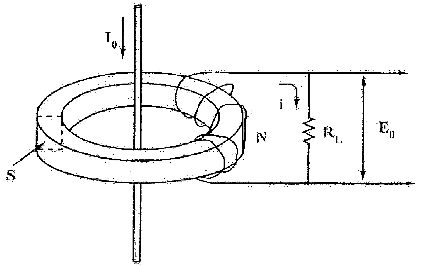
[0032]The alloy melting of Fe82-xNixSi2B16 (atomic %) was rapidly cooled by the single roll method, and the amorphous alloy ribbon with 5 mm in width and 22 μm in thickness was obtained. This amorphous alloy ribbon was wound 30 mm in the outer diameter and 21 mm in the internal diameter and the toroidal magnetic core was produced.
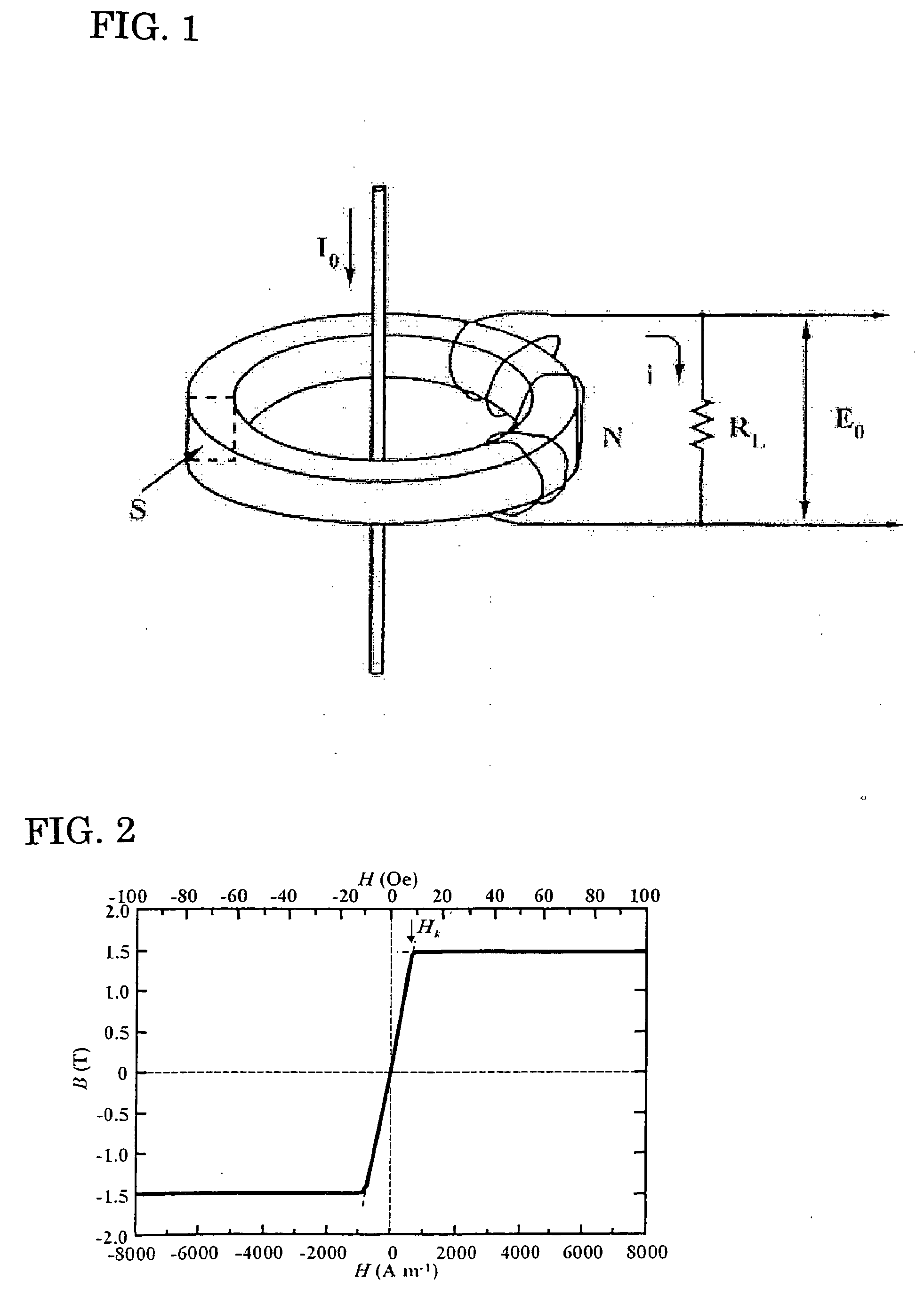
[0033]The produced magnetic core was inserted in the furnace for heat treatment in the atmosphere of nitrogen gas, and the heat treatment in magnetic field was performed. The magnetic field of 280 kAm−1 was impressed in the magnetic path of the alloy magnetic core and the perpendicular direction (the cross direction of the alloy ribbon), that is, the height direction of the magnetic core at the time of heat treatment. As a result of the X-ray diffraction, the alloy before and after heat treatment was not observed the crystal peak and was confirmed the amorphous single phase.
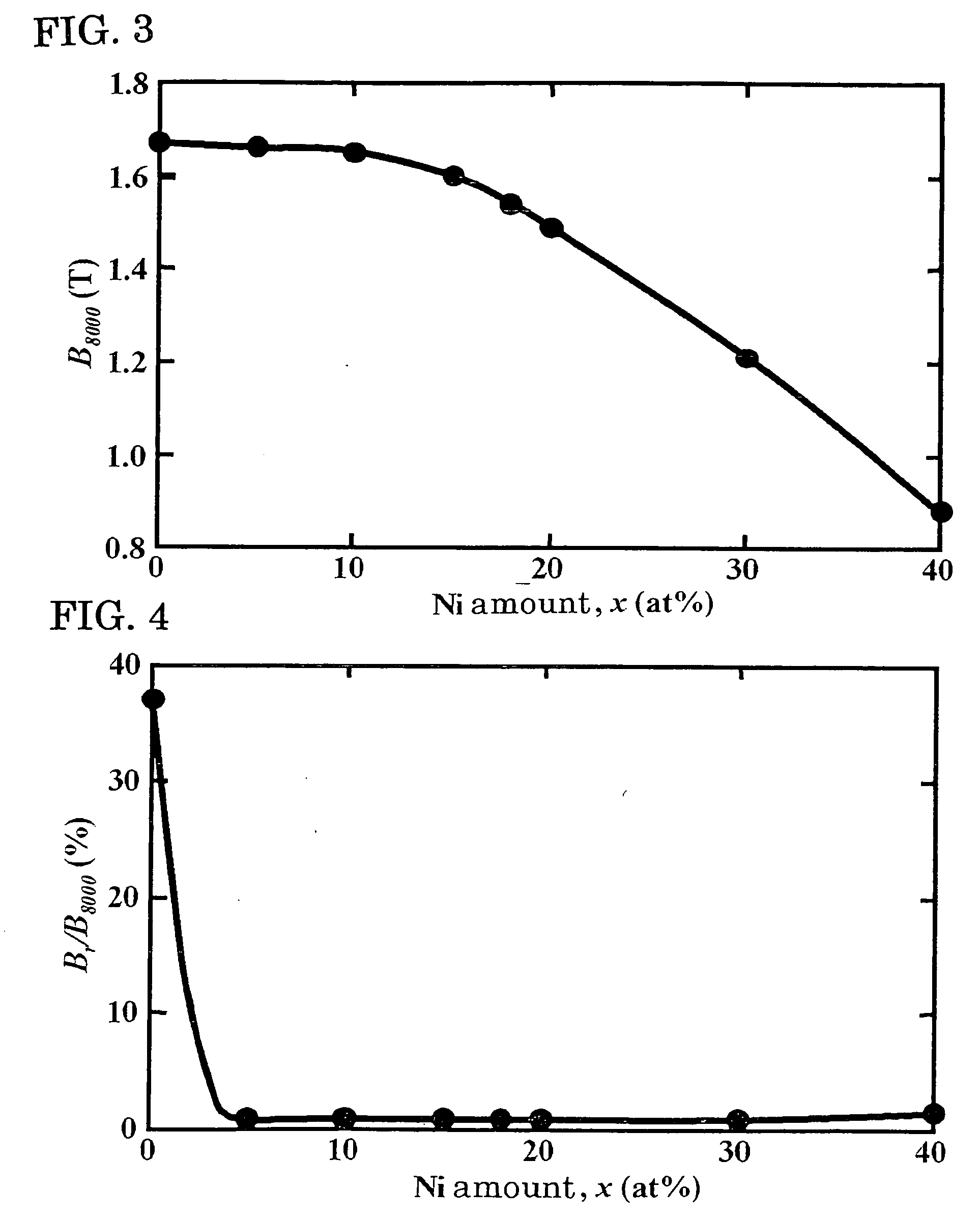
[0034]Then, the magnetic flux density B8000, the squareness ratio BrB8000−1, the coe...
embodiment 2
[0037]The alloy melting of the composition shown in Table 2 was rapidly cooled with the single roll method in Ar atmosphere, and the amorphous alloy ribbon with 5 mm in thickness and 23 μm in width was obtained. The magnetic core of the present invention was produced by winding this amorphous alloy ribbon in the outer diameter of 22 mm and the internal diameter of 18 mm. The similar heat treatment as Embodiment 1 to this alloy magnetic core was performed, and then the magnetic measurement was performed. The alloy after the heat treatment was confirmed in the amorphous state as the result of the X-ray diffraction. Fe group amorphous alloy magnetic core in addition to the present invention was also evaluated for comparison. Then, the current transformer was produced by using this magnetic core, and the phase difference of amperage rating and the absolute value of the ratio error at 23° C. was measured. The magnetic flux density B8000, the squareness ratio BrB8000−1, the relative perme...
embodiment 3
[0038]The alloy melting of Fe73.53Ni10B15.68Si0.79 (atomic %) was rapidly cooled by the single roll method, and the amorphous alloy ribbon with 5 mm in thickness and 23 μm in width was obtained. The toroidal magnetic core was produced by winding this amorphous alloy ribbon in the outer diameter of 30 mm and the internal diameter of 15 mm. The produced magnetic core was inserted in the furnace for heat treatment in the atmosphere of the nitrogen gas, and the heat treatment in magnetic field was performed. The magnetic field of 280 kAm−1 was impressed in the magnetic path of the alloy magnetic core, and the perpendicular direction (the cross direction of the alloy ribbon), that is, the height direction of the magnetic core at the time of heat treatment. The alloy after the heat treatment was not observed the crystal peak as the result of the X-ray diffraction and confirmed in the amorphous state. Then, the magnetic flux density B8000 of this alloy in 8000 Am−1, the squareness ratio Br...
PUM
| Property | Measurement | Unit |
|---|---|---|
| magnetic flux density | aaaaa | aaaaa |
| outer diameter | aaaaa | aaaaa |
| saturation flux density | aaaaa | aaaaa |
Abstract
Description
Claims
Application Information