Sight

a technology of sight and eye, applied in the field of sight, can solve the problems of inability to aim, inconvenient operation, and inability to achieve more elaborate solutions, and achieve the effect of elevating awareness of events

Active Publication Date: 2009-07-30
AIMPOINT AB
View PDF13 Cites 25 Cited by
  • Summary
  • Abstract
  • Description
  • Claims
  • Application Information

AI Technical Summary

Benefits of technology

[0006]When using high-trajectory ammunition in a field condition it is obviously important to maintain an elevated awareness regarding the events in the surroundings. Therefore it is beneficial and desired to have a sight that does not include optics or electronics distorting the field of view, e.g. an optical or electronic system that creates a real or imaginary image of the target which is not in the line of sight between the aiming eye of the user and the actual target. Also, it is beneficial to be able to look at the target with the other eye while aiming.

Problems solved by technology

A normal sight will generally not suffice, since it is difficult or impossible to have a visual contact with the target via the sight and at the same time have the correct inclination of the barrel, thus aiming is impossible.
Though functional, more elaborate solutions generally are too complicated and thus not as rugged as one would prefer for field use or too heavy to be handheld with maintained user friendliness.
The existence of moving parts inside the sight generally also increase power consumption, increase the response time, and makes the sight less versatile.

Method used


Image

  • Sight
  • Sight
  • Sight

Examples


Embodiment Construction

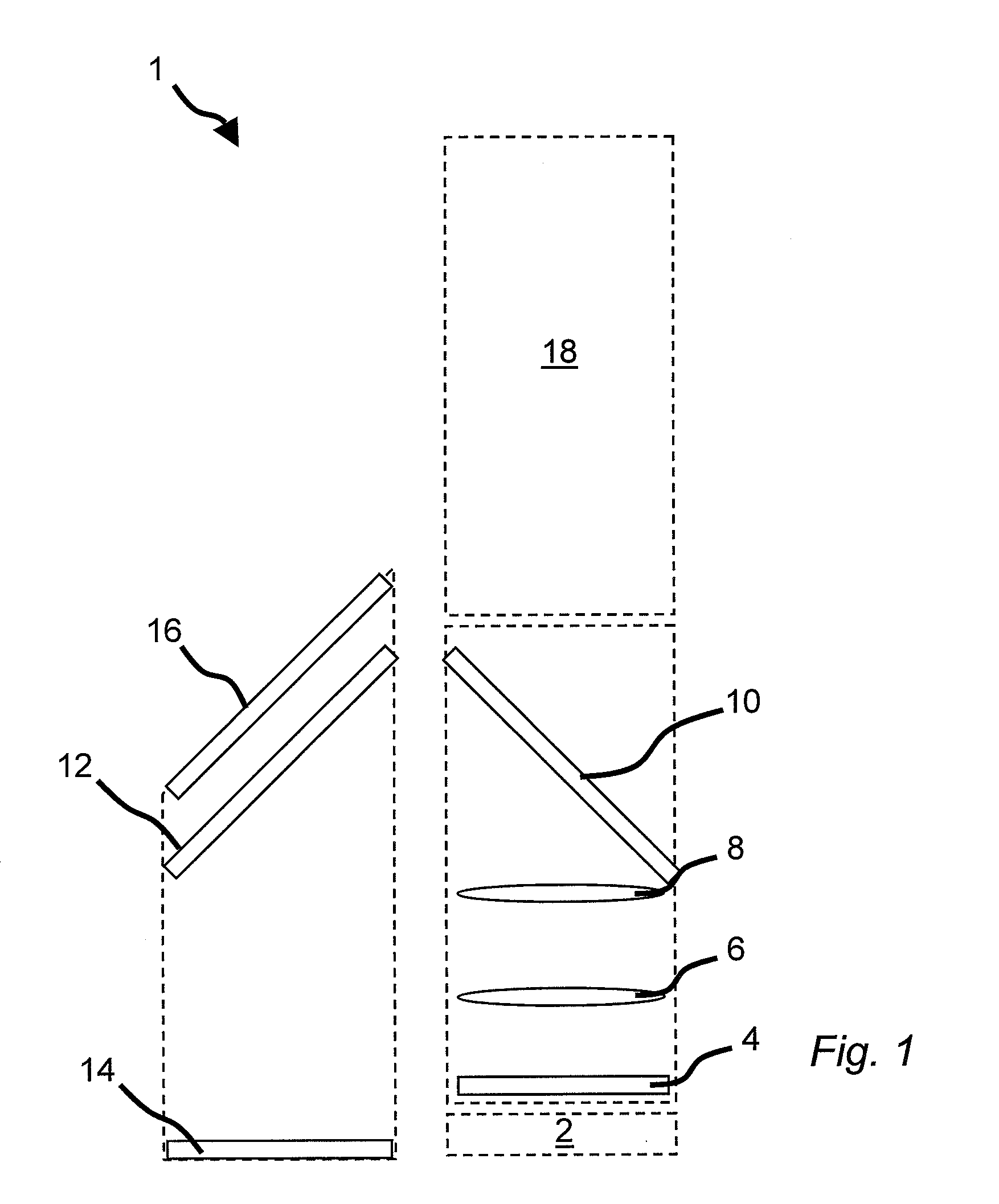
[0035]The general structure and function of the inventive sight 1 is described in reference to FIG. 1, which is a schematic representation of the sight, as viewed from above. The general purpose of the sight is to display an aiming point at the correct position. Starting from the lower right the sight has a user input interface 2, directed towards the user (downwards in FIG. 1), with a number of weather protected keypads (not shown in FIG. 1). The optic part of the sight starts with the light-emitting array 4 (“array” in the following), which is capable of emitting light in well-defined locations in a plane orthogonal to the up-down direction of FIG. 1, e.g. by means of light emitting diodes (LEDs), or backilluminated liquid crystal displays, though in the latter case it may be difficult to achieve an adequate light intensity. In one or more embodiments the light-emitting array 4 comprises a two-dimensional diode array close-packed diodes having low power consumption. Such a diode a...


PUM


Abstract

A self-compensating weapon sight comprises
    • a housing,
    • partially reflective optics, through which a user may observe a target and receive visually displayed information simultaneously,
    • a light source, for visualization of an aiming point to the user via the partially reflective optics,
    • means for receiving a measure of the distance to the target
    • a processor, for determining the adequate position of the aiming point, based on the distance to the target, and for controlling the light source to emit light so that the aiming point is visualized at the adequate position,
wherein the light source is an array capable of selectively emitting light in well defined locations on its surface.

Description

FIELD OF THE INVENTION[0001]The present invention relates to a sight, and in particular to a sight adapted for use with a weapon firing ammunition with a relatively high trajectory, such as an underslung grenade launcher (UGL) or firing with low-trajectory ammunition at longer distances. The invention also relates to a method of displaying an aiming point and to a computer program for executing said method.TECHNICAL BACKGROUND[0002]When using ammunition with low exit velocity, high trajectory or firing at targets at a significant distance, where the time of flight is significant, the weapon sight has to have certain properties. In such conditions the barrel of the weapon needs to have a considerable elevation in order for the ammunition to reach the target. A normal sight will generally not suffice, since it is difficult or impossible to have a visual contact with the target via the sight and at the same time have the correct inclination of the barrel, thus aiming is impossible. In ...

Claims


Application Information

Patent Timeline
Patent Type & Authority Applications(United States)
IPC IPC(8): G06G7/80F41G5/00
CPCF41G1/30F41G3/065F41G1/48
Inventor GUNNARSSON, KJELLWIKLUND, RALFHAKANSSON, HAKAN
Owner AIMPOINT AB
Why Eureka
Try Eureka