
Light emitting diode and method for manufacturing the same

a technology of light-emitting diodes and manufacturing methods, which is applied in semiconductor/solid-state device manufacturing, semiconductor devices, electrical apparatus, etc., can solve the problems of reducing the reliability of leds, difficult to prevent the electrostatic discharge (esd) caused by static electricity injection, and complex process

Inactive Publication Date: 2009-08-06
SEOUL VIOSYS CO LTD
View PDF10 Cites 12 Cited by
  • Summary
  • Abstract
  • Description
  • Claims
  • Application Information

AI Technical Summary

Benefits of technology

The present invention provides an LED that has a current passage connected in parallel to an active layer, which protects it from static electricity without the need for a separate Zenor diode. The LED has a current passage created by forming an electrode and a portion of the active layer in parallel to the n-type nitride layer. The contact resistance and contact area between the electrodes are changed to improve the drive conditions and provide a more reliable anti-static electricity function. The LED can be manufactured using plasma surface treatment to alter the surface resistance and contact area. The invention also provides a method for manufacturing the LED and a flip chip LED with improved protection against static electricity.

Problems solved by technology

However, for a substrate made of an insulator such as sapphire, it is difficult to prevent electrostatic discharge (ESD) caused by static electricity injected from the outside.
As a result, the LED may be damaged by the electrostatic discharge, which reduces reliability of the LED.
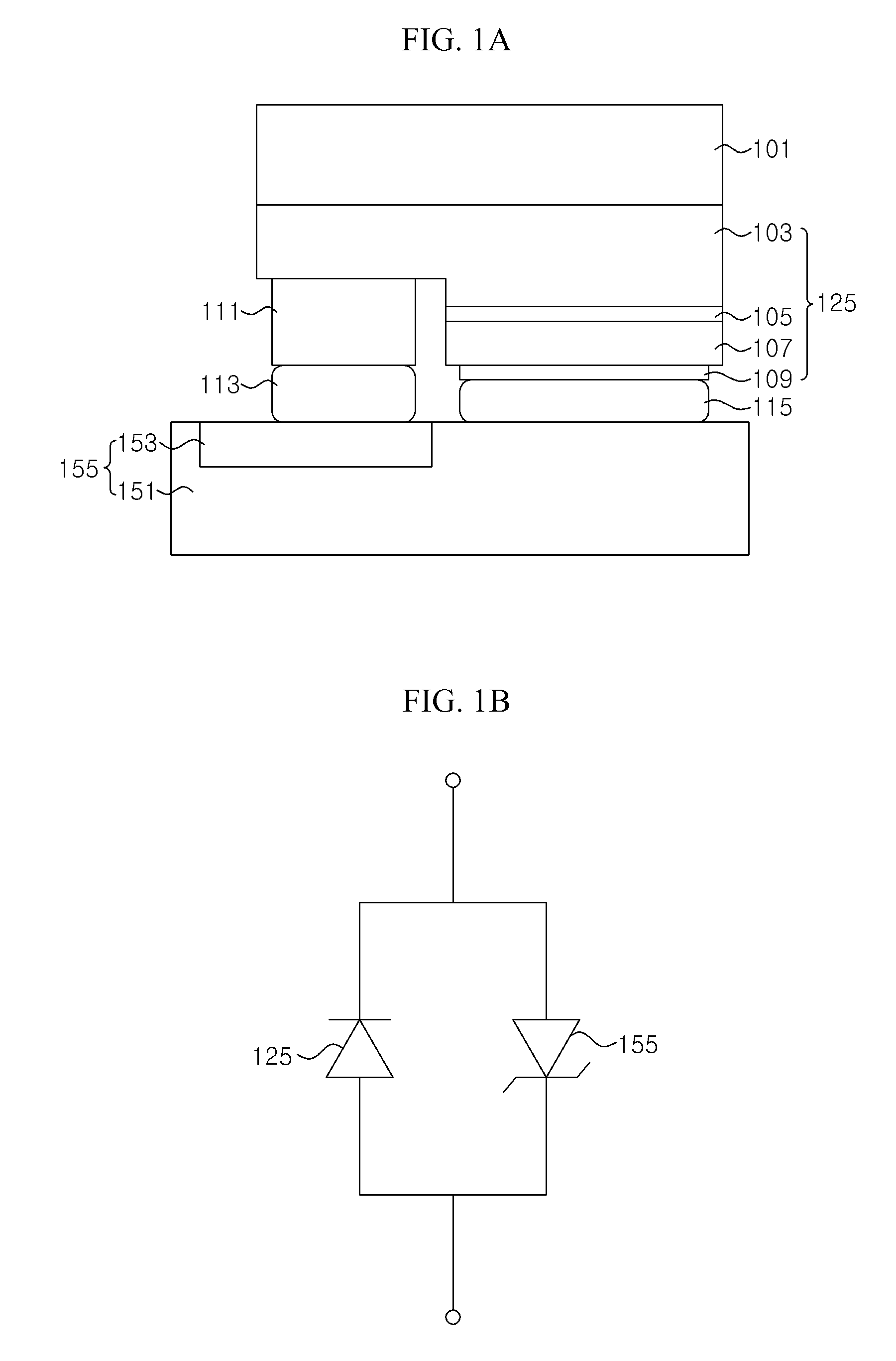
For the light emitting device shown in FIG. 1A, formation of the Zenor diode 155 on the sub-mount 151 requires an expensive ion-injection process and a diffusion process that is difficult to control, thereby leading to a complex process and an increased cost in manufacturing the sub-mount 151.
For not only the flip chip LED described above but also general surface emission LEDs, using the Zenor diode increases the number of processes and manufacturing costs for packaging the LED along with the Zenor diode, and makes it more difficult to arrange the LED and the Zenor diode in the package.

Method used


Image

  • Light emitting diode and method for manufacturing the same
  • Light emitting diode and method for manufacturing the same
  • Light emitting diode and method for manufacturing the same

Examples


Embodiment Construction

[0042]Exemplary embodiments of the present invention will be described in detail with reference to the accompanying drawings hereinafter. The embodiments are given by way of illustration for full understanding of the present invention by those skilled in the art. Hence, the present invention is not limited to these embodiments and can be realized in various forms. Further, for convenience of description, width, length, and thickness of components are not drawn to scale in the drawings. Like components are indicated by like reference numerals throughout the specification.

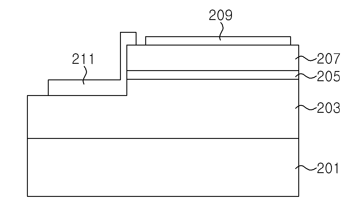
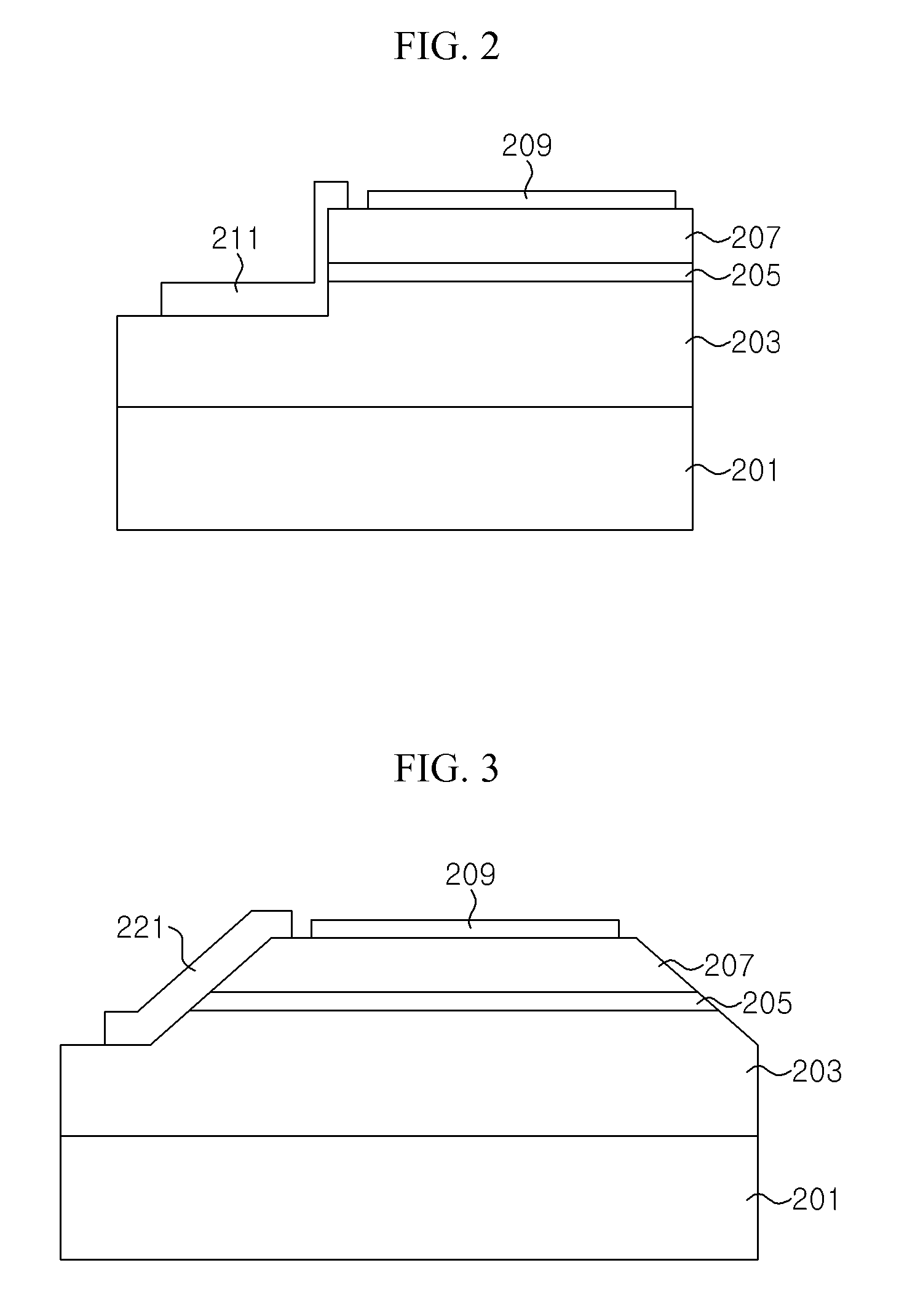
[0043]FIG. 2 is a cross-sectional view of an LED according to an embodiment of the present invention.

[0044]Referring to FIG. 2, the LED according to the embodiment includes a sapphire substrate 201, an n-type nitride layer 203, an active layer 205, a p-type nitride layer 207, a p-electrode 209, and an n-electrode 211 (a p-type pad is not shown). The n-electrode 211 is arranged on, and may contact, an exposed portion ...


PUM


Abstract

A light emitting diode includes a current leakage passage electrically connected in parallel to an active layer to better protect the light emitting diode from static electricity. The light emitting diode includes a substrate, an n-type nitride semiconductor layer on the substrate, an active layer on the n-type nitride semiconductor layer, a p-type semiconductor layer on the active layer, a p-electrode on the p-type semiconductor layer, and an n-electrode formed from the n-type semiconductor layer, exposed by etching, to a portion of the p-type semiconductor layer.

Description

CROSS REFERENCE TO RELATED APPLICATION[0001]This application claims priority from and the benefit of Korean Patent Application No. 10-2008-0010784, filed on Feb. 1, 2008, which is hereby incorporated by reference for all purposes as if fully set forth herein.BACKGROUND OF THE INVENTION[0002]1. Field of the Invention[0003]The present invention relates to a light emitting diode with an improved protection function for electrostatic discharge impact. More particularly, the present invention relates to a light emitting diode that has a current leakage passage electrically connected in parallel to an active layer to protect the light emitting diode from the static electricity and to provide better reliability in anti-electrostatic performance.[0004]2. Discussion of the Background[0005]Light emitting diodes (LEDs) are devices that convert an electric current into light when the current is input forward into an active layer of the devices. For emitting infrared rays, red light, and the lik...

Claims


Application Information

Patent Timeline
Patent Type & Authority Applications(United States)
IPC IPC(8): H01L33/00H01L33/32H01L33/36H01L33/38H01L33/42H01L33/44H01L33/62
CPCH01L27/15H01L33/44H01L33/385H01L24/14H01L2924/12035H01L2924/12041H01L2224/05573H01L2224/05568H01L2924/00014H01L24/03H01L24/06H01L24/05H01L24/13H01L2224/0603H01L2224/06102H01L2224/1703H01L2924/00H01L2224/05599
Inventor YOON, YEO JIN
Owner SEOUL VIOSYS CO LTD
Learn More