Power conversion apparatus

a power conversion and power technology, applied in the direction of dc-ac conversion without reversal, relays, pulse techniques, etc., can solve the problems of limited output power density, electromagnetic noise, increased loss of semiconductor elements, etc., and achieve low electromagnetic noise, no noise suppression filter, and high output power density

Inactive Publication Date: 2009-08-06
NAT INST OF ADVANCED IND SCI & TECH
View PDF6 Cites 52 Cited by
  • Summary
  • Abstract
  • Description
  • Claims
  • Application Information

AI Technical Summary

Benefits of technology

[0023]The present invention is intended to realize a power conversion apparatus or a power integrated circuit with the aforementioned multilevel power converter and thereby provide a power conversion apparatus with a very small electromagnetic noise requiring no noise suppression filter.
[0024]The present invention is intended to realize a power conversion apparatus or a power integrated circuit with the aforementioned multilevel power converter and thereby provide a power conversion apparatus that is free of electromagnetic noises otherwise caused by induced voltage due to the parasitic inductance of a main circuit wiring and displacement current due to the parasitic capacitance, and which poses no malfunctioning of the gate drive circuit, deteriorated insulation of a motor connected to the power conversion apparatus, or electronic erosion of a bearing.
[0025]The present invention is intended to realize a power conversion apparatus or a power integrated circuit with the aforementioned multilevel power converter and thereby provide a power conversion apparatus with a high-speed and high output power density of the motor connected to the power conversion apparatus.

Problems solved by technology

Also, the increased switching frequency increases the switching loss at the time of the switching operation of the semiconductor elements, resulting in a bulky cooling unit; therefore, the increase in output power density is limited.
In cases where the power conversion apparatus is driven with a high switching frequency, the induction voltage due to the parasitic inductance of a main circuit wiring and the displacement current due to the parasitic capacitance cause electromagnetic noise and an increased loss of the semiconductor element.
Electromagnetic noise gives rise to various problems such as the malfunction of the gate drive circuit, the deteriorated insulation of a motor connected to the power converter or the electric erosion of a bearing.
In cases where the power conversion apparatus is driven with a high switching frequency, the common mode voltage of the power conversion circuit vibrates, causing peripheral devices to be adversely affected.
As a result, the gate drive circuit connected to the main circuit switch and the main circuit of the power converter increases in size to such an extent that it becomes difficult to implement the power converter.
As a result, a transformer or similar device is used as the dedicated power supply, thereby making integration difficult.
Although an integrated two-level power converter with a gate drive circuit using this technology has been proposed, a power integrated circuit that includes an insulated power supply with increased number of gate drive circuits in the multilevel power converter has never been proposed.
In the high output power density conversion apparatus using the two-level power converter described above, the filter is reduced in size by increasing the switching frequency; therefore, the switching loss is increased at the time of the switching operation of the semiconductor element, thereby limiting the higher output power density of the power conversion apparatus.
In cases where the power conversion apparatus is driven by a high switching frequency, a great amount of electromagnetic noise is generated by the induced voltage due to the parasitic induction of the main circuit wiring, the displacement current due to the parasitic capacitance and the vibration of a common mode voltage of a power conversion circuit.
As a result, a noise suppression filter such as a common mode choke coil or EMI filter is required, which in turn limits the higher output power density of the power conversion apparatus.
The great amount of electromagnetic noise generated from the power conversion apparatus driven by a high switching frequency makes it impossible to realize a high-speed rotation of a motor connected to the power conversion apparatus, and thereby limits a higher output power density of the motor.
Nevertheless, there has been no proposal for a high output power density converter or a power integrated circuit for a multilevel power conversion circuit that includes an insulated power supply of a gate drive circuit.
Because a dedicated power supply configured with a transformer or similar device is required for the insulated power supply of the gate drive circuit, a power conversion apparatus with a number of switches that have an output power capacity of several dozen of kVA or less has not been realized.
Because a dedicated power supply configured with a transformer or similar device for the insulated power supply of the gate drive circuit is required, a power conversion apparatus with a phase voltage distortion rate of 10% or less without a passive filter for several dozen of kVA or less in the output power capacity has not been realized.
Also, because a dedicated power supply configured with a transformer or similar device is required for the insulated power supply of the gate drive circuit, a power conversion apparatus in which the electromagnetic noise has no influence on the peripheral devices without a noise suppression filter for an output power capacity of several dozen kVA or less has not been realized.

Method used


Image

  • Power conversion apparatus
  • Power conversion apparatus
  • Power conversion apparatus

Examples


example 3

(Example 3 of Power Supply to Gate Drivers)

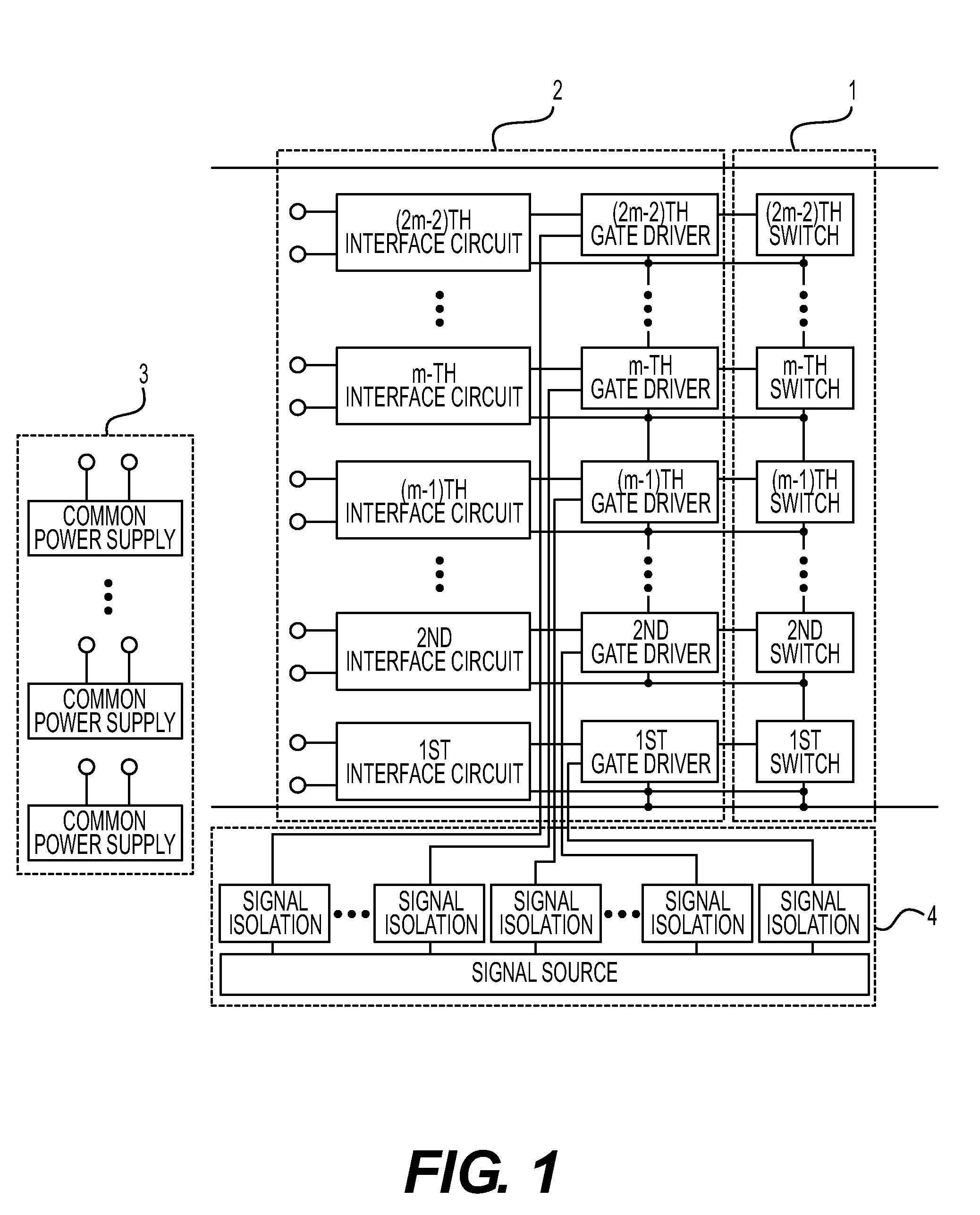
[0083]FIG. 18 shows a gate drive circuit of a multilevel power converter for supplying power to the gate drivers by connecting the interface circuit of FIG. 1 to one common power supply 30 or other interface circuits. A power supply terminal 32 of a first interface circuit is connected to a ground side terminal 31 of a common power supply 30, while a power supply terminal 34 of the first interface circuit, a power supply terminal 35 of the second interface circuit and a power supply terminal 36 of an m-th interface circuit are connected to a high voltage side terminal 33 of the common power supply 30. Further, a power supply terminal 37 of the m-th interface circuit and the terminals up to and that includes a power supply terminal 38 of a (2m−2)th interface circuit in the upper stage are connected to each other. As a result, power can be supplied from the single common power supply 30 to all of the gate drivers through each interface circui...

example 4

(Example 4 of Power Supply to Gate Drivers)

[0086]FIG. 21 shows the gate drive circuit of the multilevel power converter for supplying power to the gate drivers by connecting the interface circuit of FIG. 1 to a single common power circuit 43 and other interface circuits. A power supply terminal 45 of the first interface circuit and a power supply terminal 46 of the m-th interface circuit are connected to a ground side terminal 44 of the common power supply 43, while a power supply terminal 48 of the first interface circuit, a power supply terminal 49 of the second interface circuit and a power supply terminal 50 of the m-th interface circuit are connected to a high voltage side terminal 47 of a common power supply 43. Further, a power supply terminal 51 of the m-th interface circuit is connected to a power supply terminal 52 of an upper (2m−2)th interface circuit. As a result, power can be supplied from the single common power supply 43 to all of the gate drivers through the respect...

example 5

(Example 5 of Power Supply to Gate Drivers)

[0089]FIG. 24 shows a gate drive circuit of the multilevel power converter for supplying power to the gate drivers by connecting the interface circuit of FIG. 1 to one common power supply 57 and the other interface circuits. A power supply terminal 59 of the first interface circuit is connected to a ground side terminal 58 of a common power supply 57, while a power supply terminal 61 of the first interface circuit, a power supply terminal 62 of the second interface circuit and a power supply terminal 63 of the m-th interface circuit are connected to a high voltage side terminal 60 of the common power supply 57. Further, the power supply terminals of the second to (m−1)th interface circuits are connected with those of the interface circuits of the (m−1)th and upper stages. As a result, power can be supplied from the single common power supply 57 to all of the gate drivers through each interface circuit.

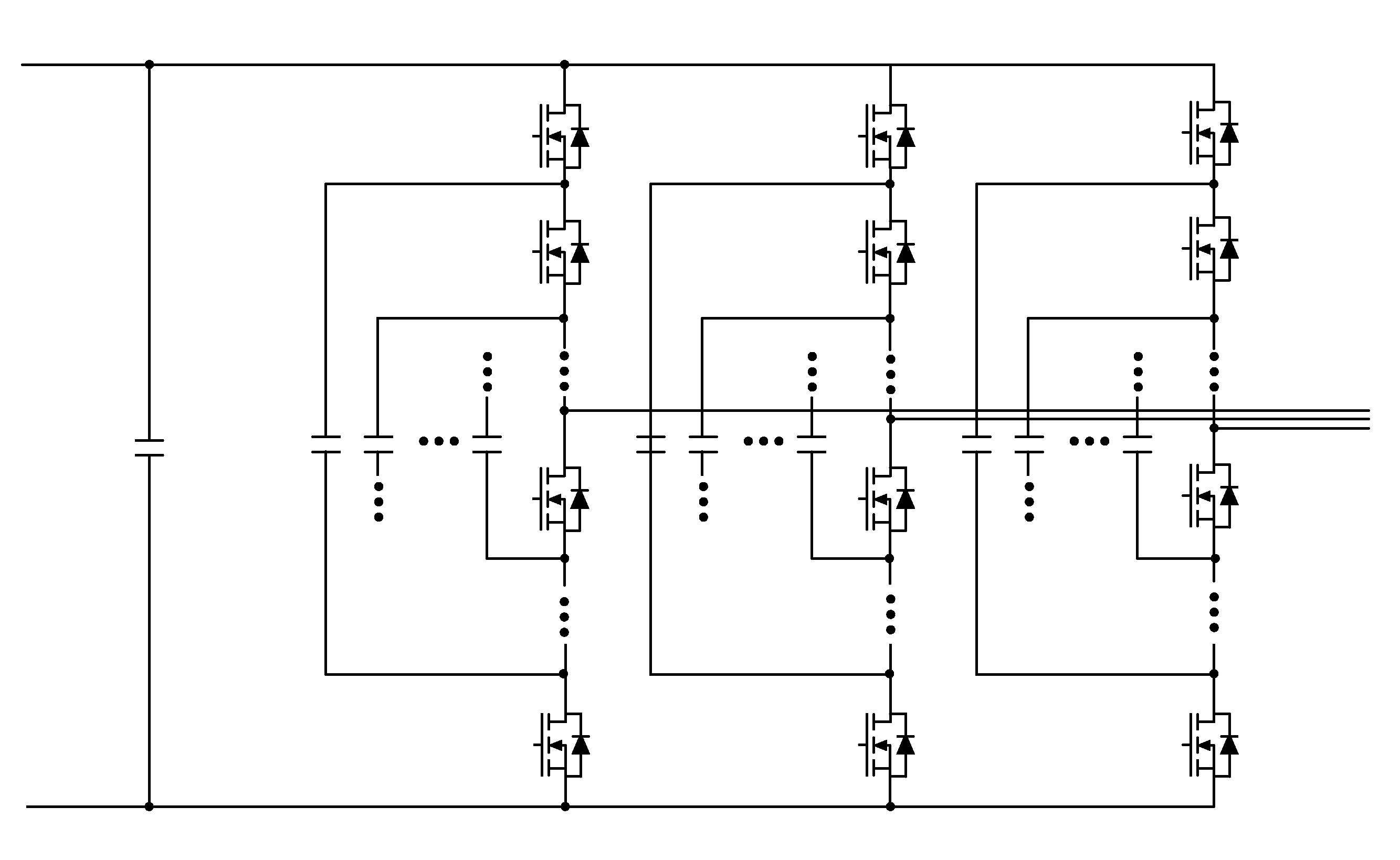
[0090]FIG. 25 shows a diode-clamp multi...


PUM


Abstract

To realize power supply to each gate drive circuit without using an individual dedicated power supply for each gate drive circuit. A power conversion apparatus includes an individual drive unit that does not require a dedicated power supply, and includes gate drivers connected to switches and interface circuits and a power converter gate drive configured with a common power supply for supplying power to the gate drive unit. Power is supplied from main circuits or a number of common power supplies fewer than that of the number of the switches through one or more power supply terminals included in the interface circuit. Also, the signal can be transmitted by isolation from a signal source to the gate drivers.

Description

BACKGROUND OF THE INVENTION[0001]1. Field of the Invention[0002]The present invention relates to a power conversion apparatus, and in particular to a power conversion apparatus for realizing a high output power density converter configured with a plurality of switches or a power integrated circuit.[0003]2. Description of the Related Art[0004]FIGS. 2 to 5 are diagrams showing the configuration of a conventional two-level power conversion circuit. FIG. 2 shows a three-phase inverter, FIG. 3 a single-phase inverter, FIG. 4 a DC-DC converter, and FIG. 5 a three-phase / three-phase power converter. In each case, the DC power source voltage Vdc is switched in two levels by turning on / off six, four, or two semiconductor elements, and further, by connecting a passive filter to the output thereof, a three-phase or single-phase AC output or DC output is obtained. A power converter conventionally achieves a high output power density with this two-level power conversion circuit by reducing the vo...

Claims


Application Information

Patent Timeline
Patent Type & Authority Applications(United States)
IPC IPC(8): H02J7/34
CPCH02M1/08H02M7/487H03K17/162H03K17/102H03K2217/0081H02M7/4837
Inventor OHASHI, HIROMICHISATO, YUKIHIKOSUNG, KYUNGMINKAMAGA, MASAMUIMAIZUMI, MOE
Owner NAT INST OF ADVANCED IND SCI & TECH
Why Eureka
Try Eureka