Receiver optical sub-assembly and optical receiver module

Inactive Publication Date: 2009-08-06
FUJITSU LTD
View PDF8 Cites 6 Cited by
  • Summary
  • Abstract
  • Description
  • Claims
  • Application Information

AI Technical Summary

Benefits of technology

[0009]The receiver optical sub-assembly may further comprise an electrically conductive cylindrical member standing from the electrically conductive base within the inner space defined in the cap so as to surround the multilayered ceramic substrate and the light receiving element along the electrically conductive base, the electrically conductive cylindrical member connected to the ground layer through an electrically conductive material so as to serve as a part of the electrically conductive body. The multilayered ceramic substrate and the light receiving element are hermetically enclosed in the cap in the receiver optical sub-assembly. The cylindrical member allows an operator to observe the condition of bonding between the electrically conductive material and the ground layer as well as between the electrically conductive material and the cylindrical member prior to enclosing process of the multilayered ceramic substrate and the light receiving element. Electric continuity is accordingly reliably established from the ground layer to the base. In this case, the electrically conductive material is an electrically conductive

Problems solved by technology

Such a long-distance optical transmission suffers from distortion of a received optical signal.
The

Method used


Image

  • Receiver optical sub-assembly and optical receiver module
  • Receiver optical sub-assembly and optical receiver module
  • Receiver optical sub-assembly and optical receiver module

Examples


Embodiment Construction

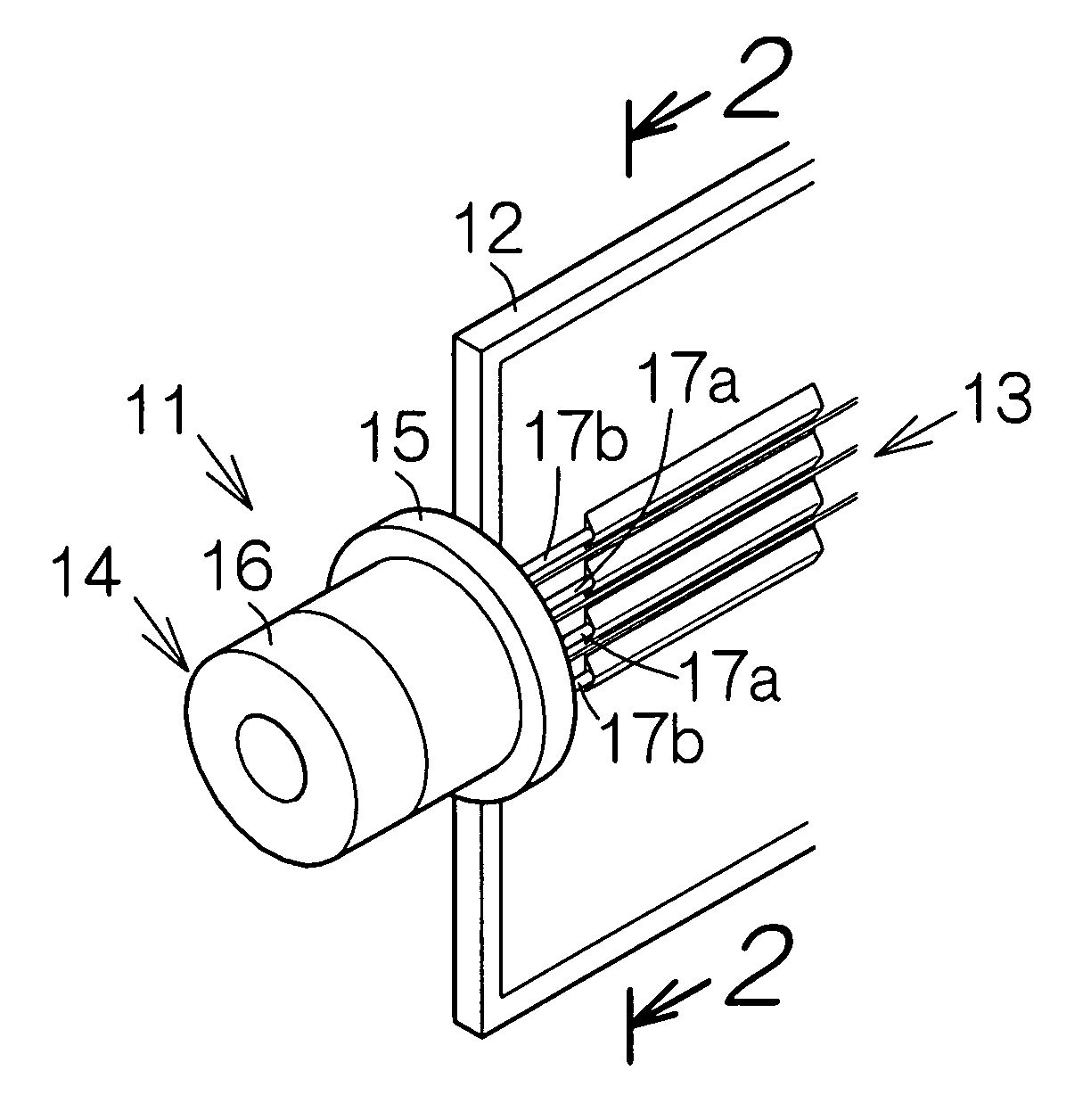
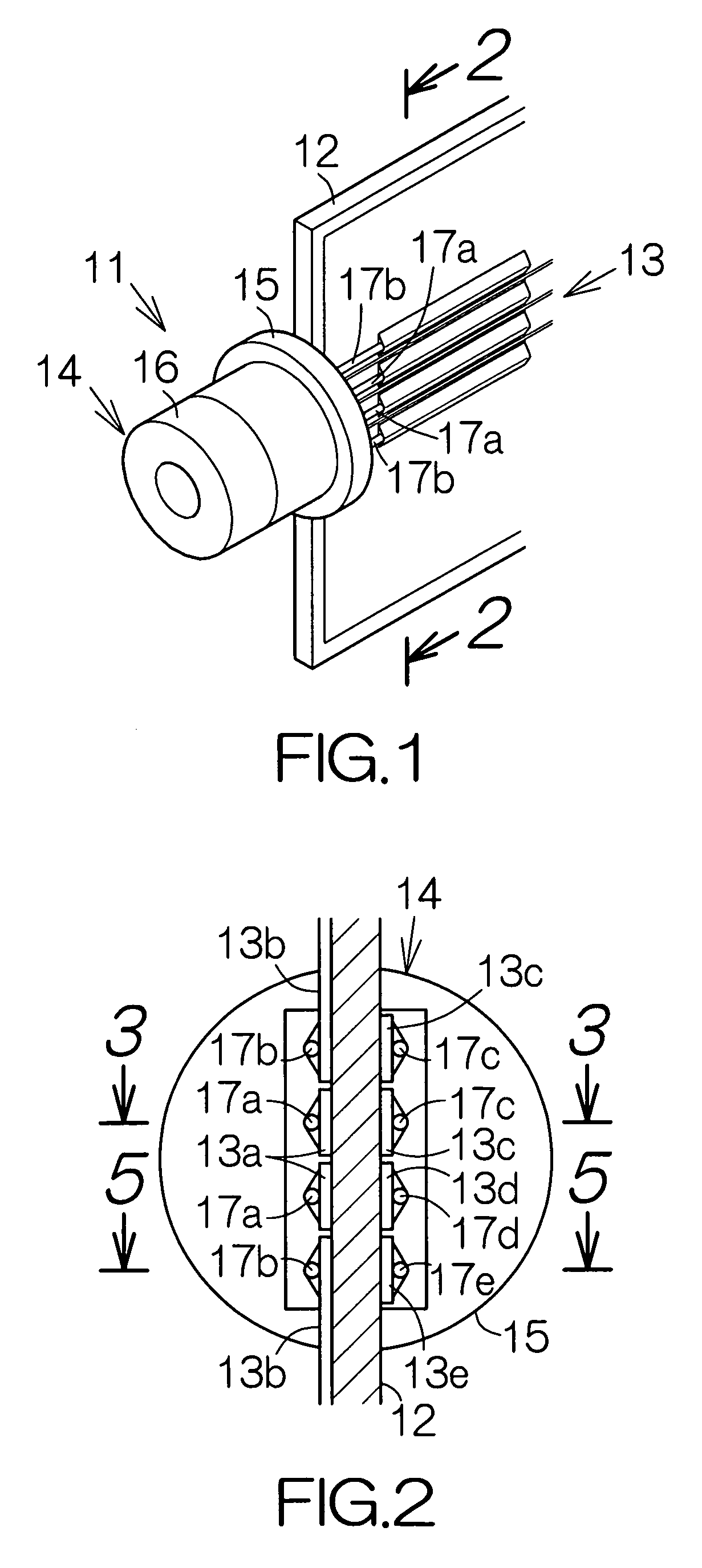
[0029]FIG. 1 schematically illustrates an optical receiver module 11. The optical receiver module 11 includes a printed wiring board 12 contoured in a rectangle, for example. Wiring patterns 13 are formed on the front surface of the printed wiring board 12 and the back surface, not shown, of the printed wiring board 12. The front and back surfaces of the printed wiring board 12 extend in parallel with each other. The printed wiring board 12 defines four end surfaces perpendicular to its front and back surfaces. The four end surfaces connect the front and back surfaces to each other. A receiver optical sub-assembly (ROSA) 14 according to a first embodiment of the present invention is attached to one of the end surfaces of the printed wiring board 12.

[0030]The receiver optical sub-assembly 14 includes a base 15 in the form of a disk. The base 15 is superposed on the end surface of the printed wiring board 12. The base 15 takes an attitude intersecting the printed wiring board 12. Here...


PUM


Abstract

A receiver optical sub-assembly includes a multilayered ceramic substrate mounted on an electrically conductive base. The multilayered ceramic substrate has a ground layer on the front surface. A light receiving element is mounted on the front surface of the multilayered ceramic substrate. A cap and the electrically conductive base enclose the multilayered ceramic substrate and the light receiving element. An electrically conductive body connects the ground layer to the electrically conductive base. Terminals are attached to the back surface of the multilayered ceramic substrate. The terminals project outside the electrically conductive base. A high frequency noise propagates from the ground layer to the base through the electrically conductive body. A sufficient amount of ground potential is obtained. Self-resonance is prevented. The multilayered ceramic substrate enables an enhanced density of the terminals based on a wiring pattern or patterns and a via or vias.

Description

BACKGROUND OF THE INVENTION[0001]1. Field of the Invention[0002]The present invention relates to a receiver optical sub-assembly suitable for a long-distance optical transmission.[0003]2. Description of the Prior Art[0004]An optical receiver device such as a receiver optical sub-assembly (ROSA) is well known. A photodiode is incorporated in the receiver optical sub-assembly. The photodiode outputs electric current in response to reception of light. The electric current output from the photodiode is converted into voltage through an amplifier. The output from the amplifier is utilized to discriminate the binary data of a signal. The photodiode is mounted on a glass hermetic package substrate, for example. A sealing cap is utilized to hermetically enclose the glass hermetic package substrate under a nitrogen atmosphere. A long-distance optical transmission of a transmission distance of 80 km or longer, for example, is well known. Such a long-distance optical transmission suffers from ...

Claims


Application Information

Patent Timeline
IPC IPC(8): H04B10/00G01J1/44H01L31/02
CPCG01J1/02G01J1/0219G01J1/0271H05K1/182G01J1/0411G01J5/045H01L31/101G01J1/04
Inventor NAKAO, TAKUYA
Owner FUJITSU LTD
Why Eureka
Try Eureka