Digitally Clock with Selectable Frequency and Duty Cycle

Active Publication Date: 2009-08-13
MACOM CONNECTIVITY SOLUTIONS LLC
View PDF8 Cites 22 Cited by
  • Summary
  • Abstract
  • Description
  • Claims
  • Application Information

AI Technical Summary

Benefits of technology

[0008]The multi-modulus divider is presented that divides a signal using division ratios such as 0.75, 0.875, 1, 1.125, and 1.25, dynamically in response to a control signal, by selecting between different phases of a reference frequency. With the addition of fixed ratio dividers, for example divide by 8, division ratios of 6, 7, 8, 9, and

Problems solved by technology

However, the pulse-swallowing technique may generate undesirable harmonic frequencies components.
Further, it may not be possible to conveniently generate every required frequency using just th

Method used


Image

  • Digitally Clock with Selectable Frequency and Duty Cycle
  • Digitally Clock with Selectable Frequency and Duty Cycle
  • Digitally Clock with Selectable Frequency and Duty Cycle

Examples


Embodiment Construction

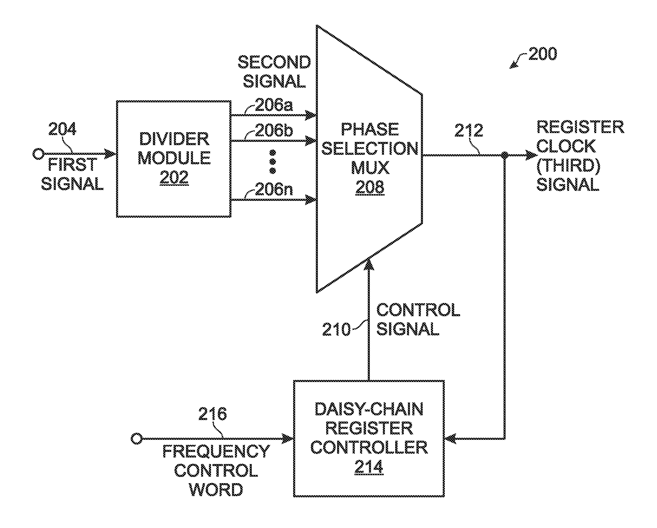
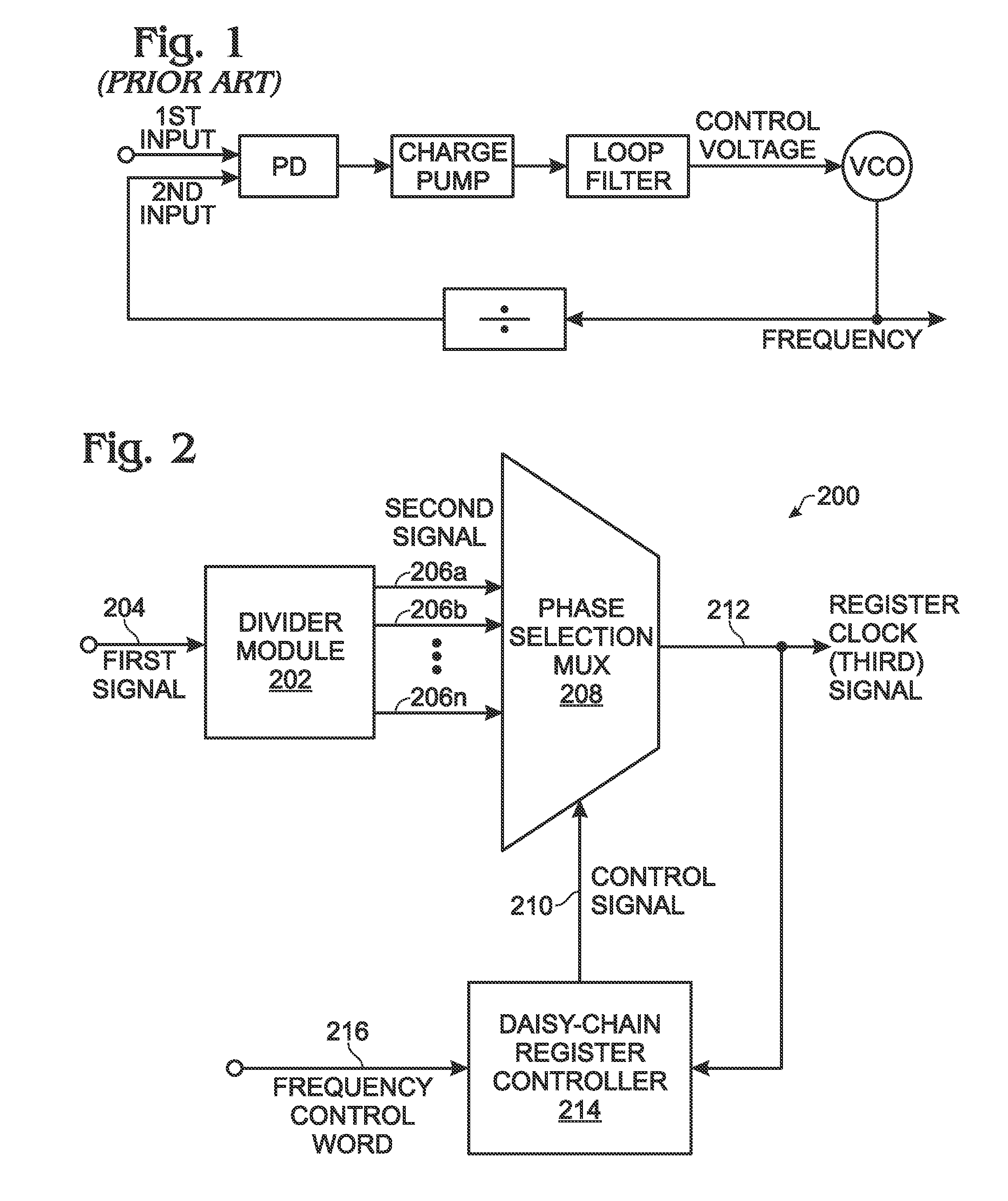
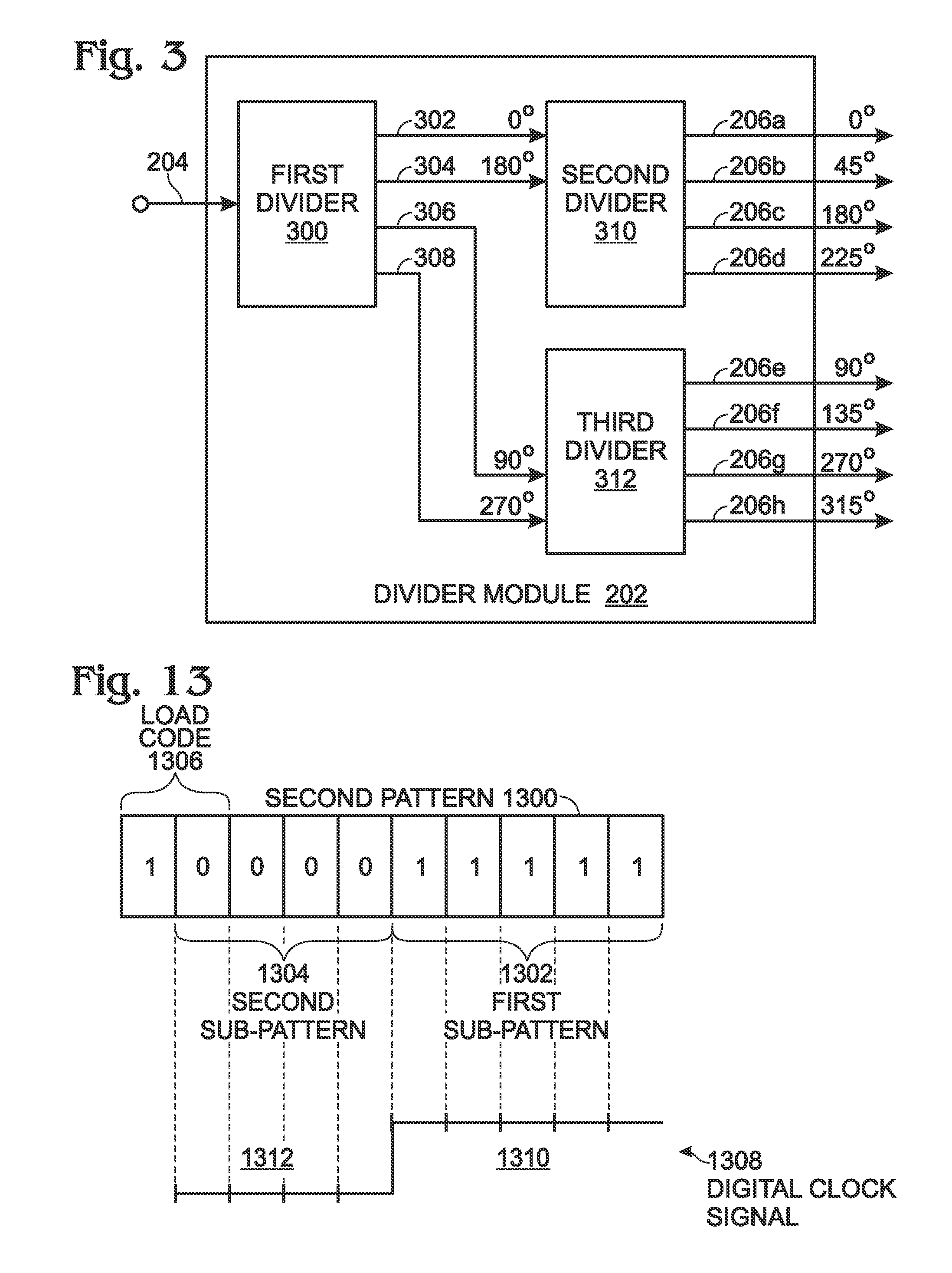
[0030]FIG. 2 is a schematic block diagram of a system for multi-modulus division. The system 200 comprises a divider module 202 having an input on line 204 to accept a first signal (first clock signal) having a first frequency. Referencing FIG. 1 briefly, line 204 may be a VCO output for example. The divider module 202 divides the first frequency by an integral number n and supplies a second signal with a plurality of phase outputs on line 206, each having a second frequency. Phase output lines 206a through 206n are shown, where n is not limited to any particular number. In one aspect not shown, the divider module 202 divides the first clock signal by m and a second fixed divider following the MUX, divides the second signal by q, where n=m·q. In another aspect not shown, the divider module divides the first clock signal by 1, and a second fixed divider following the MUX divides the second signal by n.

[0031]A phase selection multiplexer (MUX) 208 has an input on lines 206 to accept t...


PUM


Abstract

A system and method are provided for controlling the duty cycle and frequency of a digitally generated clock. The method accepts a first clock signal having a fixed first frequency. A frequency control word with a first pattern is loaded into a first plurality of serially-connected registers. A duty cycle control word with a second pattern is loaded into a second plurality of serially-connected registers. A register clock signal is generated in response to the first clock and the first pattern. Then, a digital clock signal is generated having a frequency and duty cycle responsive to the register clock signal and the second pattern.

Description

RELATED APPLICATIONS[0001]This application is a Continuation-in-Part of a pending application entitled, HIGH SPEED MULTI-MODULUS PRESCALAR DIVIDER, invented by An et al., Ser. No. 11 / 717,261, filed Mar. 13, 2007, attorney docket no. applied—198, which is incorporated herein by reference.BACKGROUND OF THE INVENTION[0002]1. Field of the Invention[0003]This invention generally relates to electronic circuitry and, more particularly, to a system and method for using multi-modulus prescalar division as a basis for generating a high-speed digital clock signal with a selectable frequency and duty cycle.[0004]2. Description of the Related Art[0005]FIG. 1 is a schematic block diagram of a conventional phase locked loop (prior art). A phase detector (or frequency detector) receives a first input signal, such as might be supplied on a serial data stream or a clock source, and compares it to a second input signal supplied by the divider. The phase detector (PD) generates an output that is respon...

Claims


Application Information

Patent Timeline
IPC IPC(8): G06F1/04
CPCG06F1/08
Inventor DO, VIET LINHAN, HONGMINGLEW, JIM
Owner MACOM CONNECTIVITY SOLUTIONS LLC
Why Eureka
Try Eureka