
Optical measuring device for determining temperature in a cryogenic environment and winding arrangement whose temperature can be monitored

a technology of optical measurement and temperature measurement, which is applied in the direction of instruments, heat measurement, optical elements, etc., can solve the problems of high vaporization loss of cryogenic coolant, difficult to locate, and the location of quench can be likewise locally limited

Inactive Publication Date: 2009-08-13
SIEMENS AG
View PDF5 Cites 23 Cited by
  • Summary
  • Abstract
  • Description
  • Claims
  • Application Information

AI Technical Summary

Benefits of technology

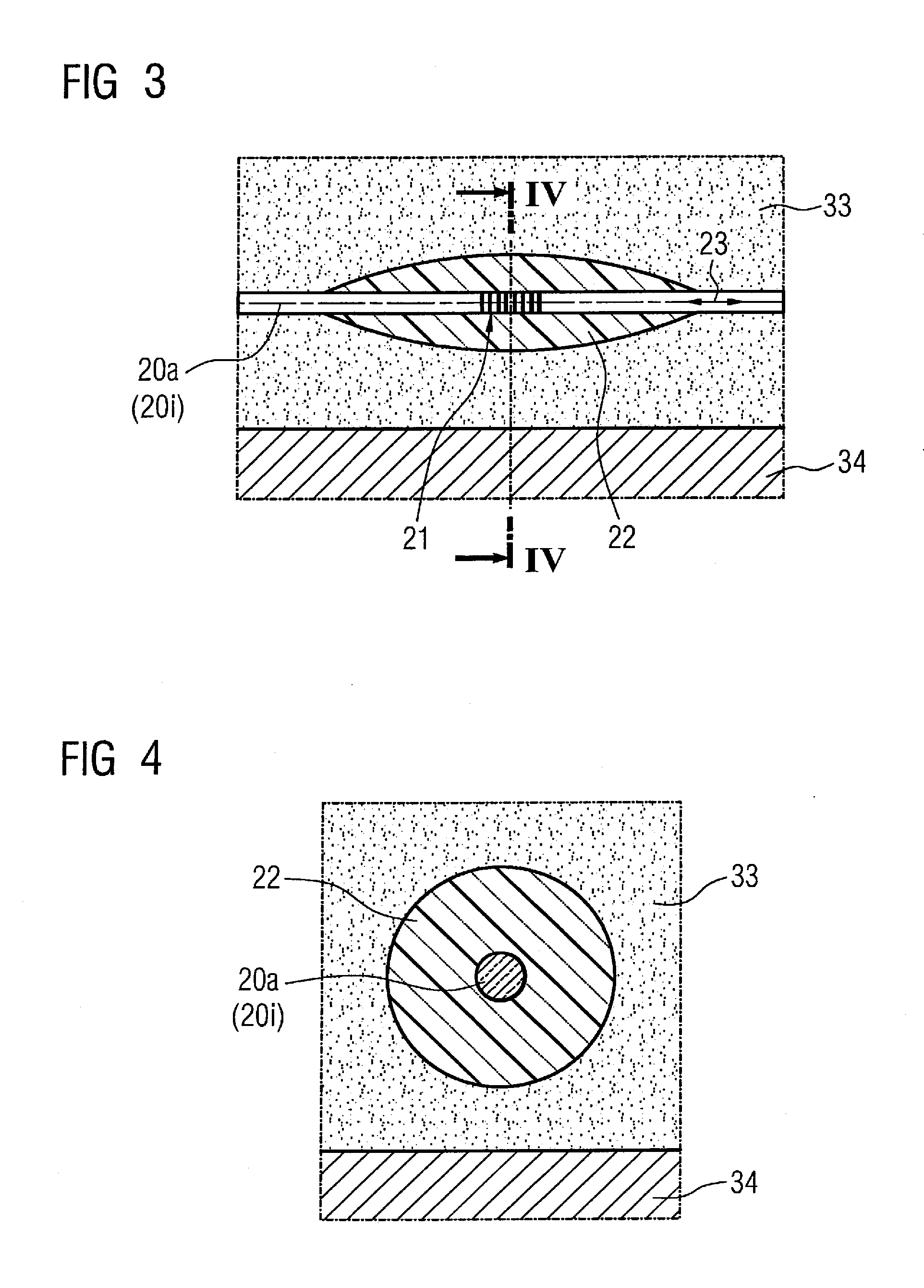
[0010]Furthermore, it is advantageous for the at least one jacket element to exhibit a pronounced expansion in the length direction of the at least one optical wave guide in the region of the at least one fiber Bragg grating sensor. The thickness of the at least one jacket element is thus kept as small as possible in the region of the associated at least one fiber Bragg grating sensor in order to minimize the heat capacity of the at least one jacket element. An optimally short response time of the at least one fiber Bragg grating sensor is thereby ensured.
[0012]It is additionally advantageous for the at least one jacket element to be fashioned to be rotationally symmetrical around the at least one optical wave guide. In particular, the at least one jacket element tapers conically at both ends. Due to such a symmetrical design of the at least one jacket element, the expansion and contraction forces emanating from the at least one jacket element that act on the at least one optical wave guide are distributed uniformly over its extent. The expansion and contraction of the at least one fiber Bragg grating sensor therefore ensues uniformly so that the light signal (reflected on at least one fiber Bragg grating senor, for example) exhibits an optimally small bandwidth.
[0015]It is advantageous when the light signal from the injection means is injected in pulses into the at least one optical wave guide with a pulse frequency in a range from 500 Hz to 10 kHz. It is thus ensured that the change of the temperature distribution can be temporally resolved given a high propagation speed of a temperature change, as it occurs given a quench process in a superconductor, for example.
[0018]It is advantageous to arrange the at least one optical wave guide internally and / or externally on the winding body.
[0020]It is advantageous when at least one optical wave guide is embedded in the composite material. The at least one optical wave guide can thus be positioned optimally close to the at least one conductor, and the at least one optical wave guide is protected from external influences and additionally is mechanically stabilized by the composite material. Due to the embedding it is additionally ensured that the at least one optical wave guide and in particular the at least one fiber Bragg grating sensor are arranged at a fixed, invariable distance from the at least one electrical conductor to be monitored.

Problems solved by technology

This is associated with a severe heating of the superconductor which results in a high vaporization loss of cryogenic coolant.
Particularly in magnetic resonance apparatuses, this proves to be quite difficult since magnetic resonance apparatuses are normally composed of numerous coils arranged in complicated geometry.
The location of the quench can therefore likewise be locally limited.
However, this leads to a large number of voltage taps, particularly in magnetic resonance apparatuses, which makes the winding process very complicated.
Since the temperature-dependent wavelength change of “naked” fiber Bragg grating sensors in the range of cryogenic temperatures (i.e. temperatures that are at 120 K and lower) is not present in practice, the optical device specified in this document is not suitable for use in such a cryogenic environment.

Method used


Image

  • Optical measuring device for determining temperature in a cryogenic environment and winding arrangement whose temperature can be monitored
  • Optical measuring device for determining temperature in a cryogenic environment and winding arrangement whose temperature can be monitored
  • Optical measuring device for determining temperature in a cryogenic environment and winding arrangement whose temperature can be monitored

Examples


Embodiment Construction

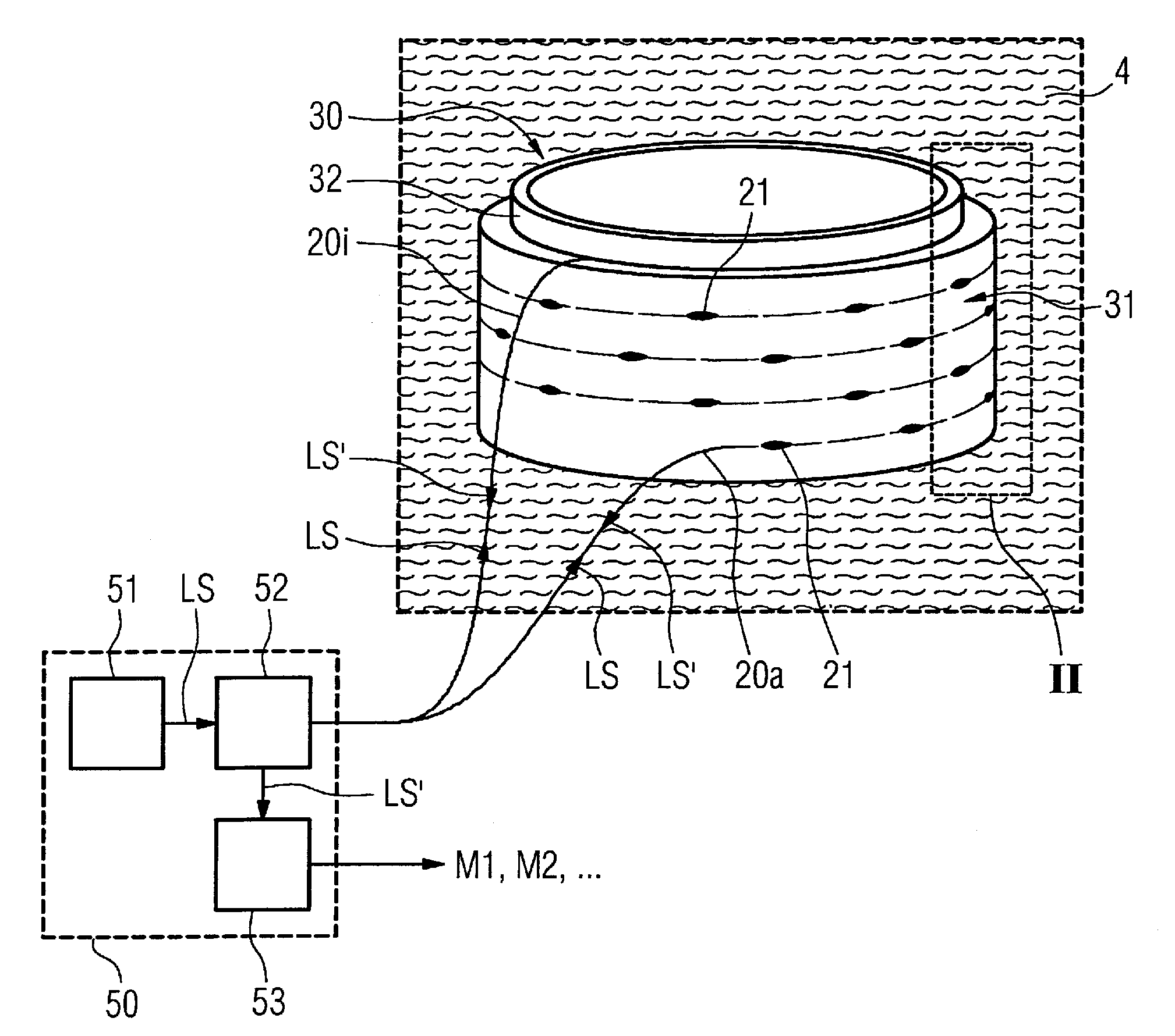
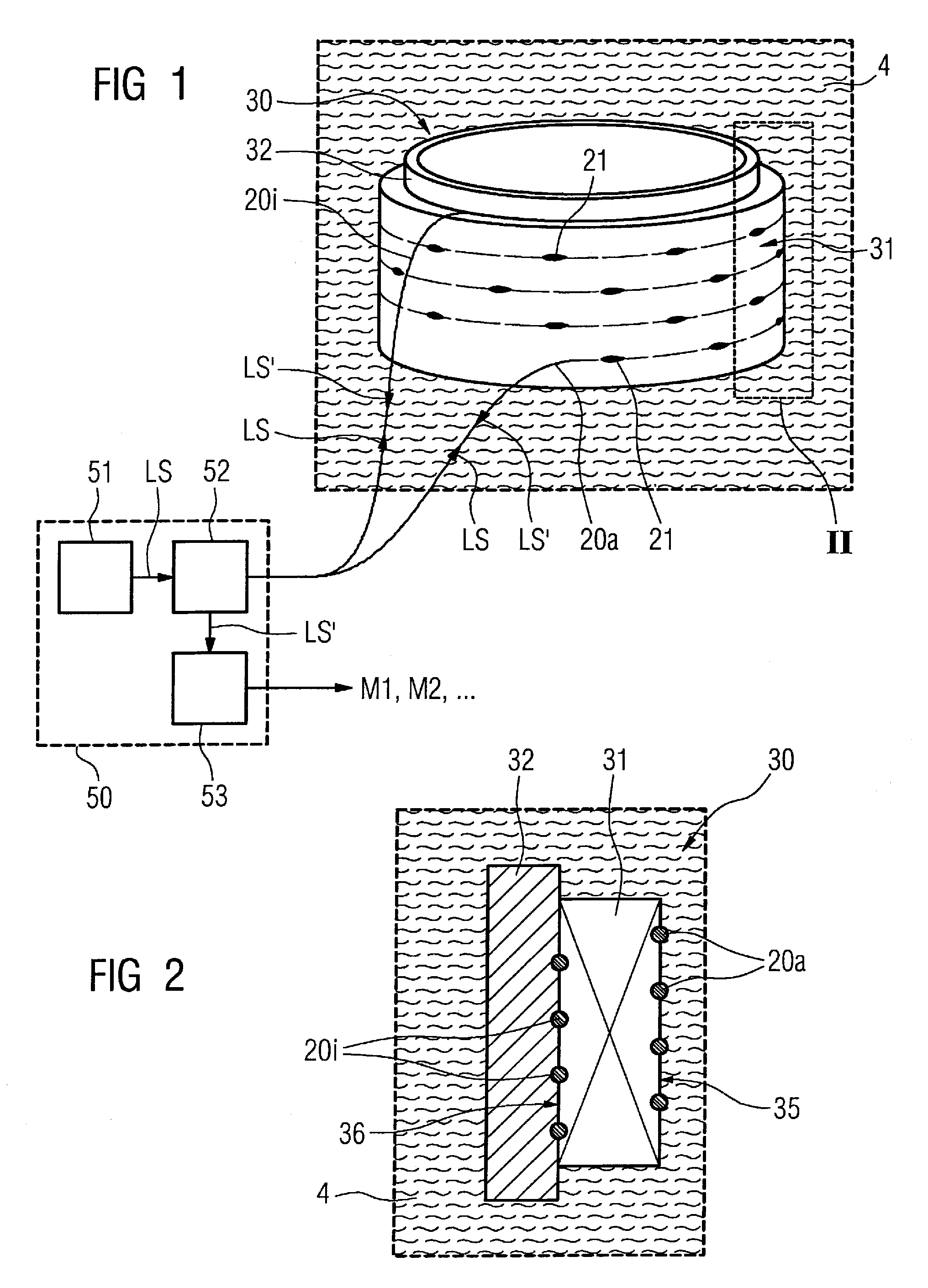
[0027]According to the invention, an optical measurement device with a winding arrangement 30 in a cryogenic medium 4 (for example liquid helium or liquid nitrogen) is shown in FIG. 1. The winding arrangement 30 thereby exhibits a winding body 31 arranged on a winding support 32. However, the winding body can also be executed in a self-supporting manner, i.e. without winding support 32 (not shown in FIG. 1). The winding body 31 is thereby fashioned from a plurality of windings of a superconductive conductor 34 (see FIG. 3). The superconductive conductor 34 can thereby be a low-temperature superconductor or a high-temperature superconductor. Depending on the superconductor type, the conductor 34 can be band-shaped, be executed with rectangular cross-section or even exhibit a round cross-section. Both winding supports 32 and winding bodies 31 are of a hollow cylinder shape in the presented exemplary embodiment. The winding body 31 respectively possesses an optical wave guide 20i, 20a ...


PUM


Abstract

An optical measuring device for determining temperature in a cryogenic environment includes at least one optical waveguide provided with at least one fiber Bragg grating sensor that is interrogated by a light signal. The device includes a light injector that injects light into the at least one fiber Bragg grating sensor, and an evaluation unit that determines a temperature value from the modulated light signal emanating from the at least one fiber Bragg grating sensor. The device includes at least one jacket that non-rigidly encloses the optical waveguide, at least in the region of the at least one fiber Bragg grating sensor. The jacket has a larger coefficient of thermal expansion, at least at cryogenic temperatures, than the optical waveguide. A winding arrangement for use in a cryogenic environment is provided with such a device for temperature monitoring of a conductor of the winding arrangement.

Description

BACKGROUND OF THE INVENTION[0001]1. Field of the Invention[0002]The invention concerns an optical measurement device for temperature determination in a cryogenic environment. The measurement device is of the type having at least one optical wave guide provided with at least one fiber Bragg grating sensor, via which the at least one fiber Bragg grating can be interrogated by means of a light signal. The measurement device furthermore has a light injector that injects the light signal into the at least one optical wave guide, and evaluation unit to determine a temperature value from a light sensor arriving from at least one fiber Bragg grating sensor. The invention also concerns a winding arrangement whose temperature can be monitored.[0003]2. Description of the Prior Art[0004]Superconductive magnets that are used, for example, in magnetic resonance tomography systems are cooled to a temperature of 120 K or lower with a cryogenic coolant, depending on the employed superconductor type....

Claims


Application Information

Patent Timeline
IPC IPC(8): G02B6/00G01K11/00
CPCG01K2203/00G01K11/3206
Inventor BOSSELMANN, THOMASHERTSCH, HAGENLEGHISSA, MARTINOOOMEN, MARIJN PIETERWILLSCH, MICHAEL
Owner SIEMENS AG
Learn More