Semiconductor laser diode with a ridge structure buried by a current blocking layer made of un-doped semiconductor grown at a low temperature and method for producing the same

a laser diode and semiconductor technology, applied in semiconductor lasers, laser details, nanooptics, etc., can solve the problems of poor thermal conductivity of materials compared to metals or semiconductors, degrade the crystal quality of grown layers, and difficult to secure device reliability, etc., to achieve the effect of ensuring reliability

Inactive Publication Date: 2009-08-13
SUMITOMO ELECTRIC IND LTD
View PDF4 Cites 10 Cited by
  • Summary
  • Abstract
  • Description
  • Claims
  • Application Information

AI Technical Summary

Benefits of technology

[0009]One aspect of the present invention relates to a semiconductor optical device that provides a ridge waveguide structure and a current blocking layer formed so as to bury the ridge waveguide structure. The current blocking layer of the invention may be made of un-doped group III-V compound semiconductor material, one of un-doped GaInP and un-doped AlGaInP grown at a relatively low temperature. Because these un-doped semiconductor material grown at a low temperature, between 500° C. and 600° C., shows substantially semi-insulating characteristic with the resistance thereof greater than 105 Ω·cm, the optical device may provide the current blocking layer without any pn-junction, impurity doped layer nor materials except for the semiconductor, whereby the device may operate in higher modulation frequencies and enhance the reliability thereof.
[0011]The active region may include a double quantum well structure comprising two well layers made of un-doped GaInNAs and a GaAs barrier layer put between the GaInNAs well layers. Because the GaInNAs layer is so sensitive to the thermal stress, the low temperature growth for the current blocking layer of the invention may escape the well layers from being affected by the thermal stress, whereby the device may show a preferable reliability.

Problems solved by technology

Although the current blocking layer disclosed therein may be made of dielectric material, such material generally shows poor thermal conductivity compared to metals or to semiconductors.
Thus, the current blocking layer made of dielectric material may cause unavoidable stress to the ridge waveguide structure, which may degrade the crystal quality of the grown layer and makes it hard to secure the reliability of the device.
However, this arrangement to form the reversely biased pn-junction for the current blocking function is unavoidable to increase the parasitic capacitance due to the carriers accumulated in the pn-junction.
Accordingly, the laser diode with the current blocking function by the reversely biased pn-junction is unsuitable for the high speed application.

Method used


Image

  • Semiconductor laser diode with a ridge structure buried by a current blocking layer made of un-doped semiconductor grown at a low temperature and method for producing the same
  • Semiconductor laser diode with a ridge structure buried by a current blocking layer made of un-doped semiconductor grown at a low temperature and method for producing the same
  • Semiconductor laser diode with a ridge structure buried by a current blocking layer made of un-doped semiconductor grown at a low temperature and method for producing the same

Examples


first embodiment

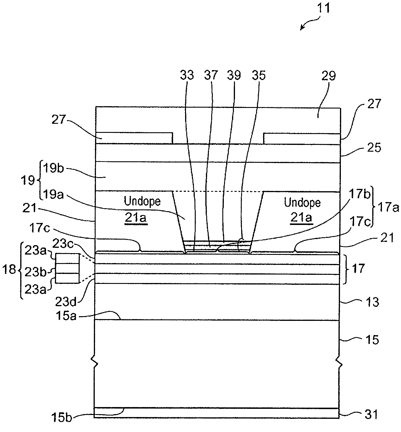
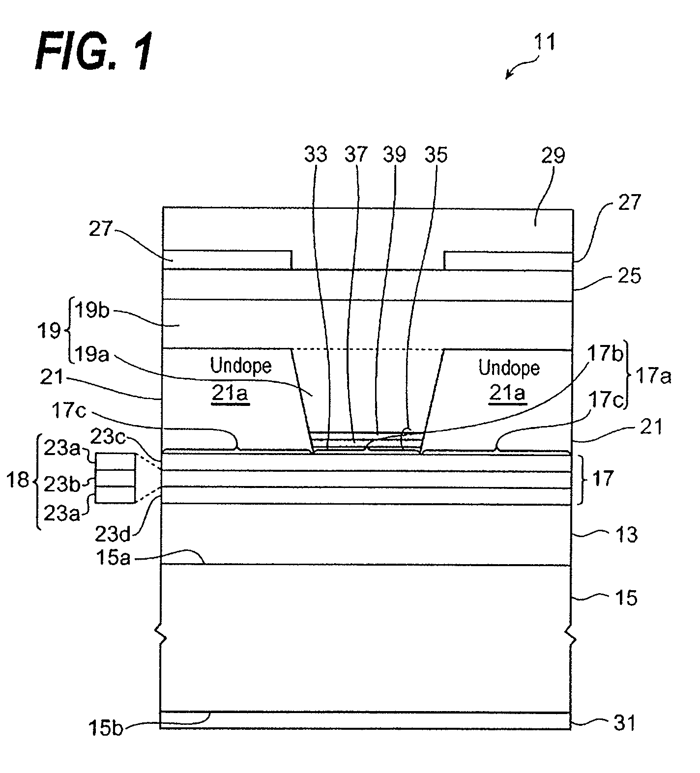
[0019]FIG. 1 is a cross section showing a semiconductor optical device according to one embodiment of the present invention. The semiconductor optical device 11 includes; a lower cladding layer 13 with the first conduction type on the primary surface 15a of the GaAs substrate 15; the active region 17, which is formed on the lower cladding layer 13, includes the first and second regions, 17b and 17c, respectively, in the primary surface 17a thereof; the upper cladding layer 19 with the second conduction type that includes a first portion 19a constituting the ridge waveguide structure on the first region 17b; and the current blocking layer 21, which is provided on the second region 17c of the active region 17 and includes a semiconductor layer 21a made of un-doped group III-V compound semiconductor material with high resistance.

[0020]In the semiconductor device 11, the current blocking layer 21 buries the first portion 19a, the ridge waveguide structure, of the upper cladding layer 19...

second embodiment

[0053]FIG. 5 illustrates a semiconductor optical device according to the second embodiment of the present invention. The optical device 11c shown in FIG. 5 provides, similar to the device of the first embodiment, the lower cladding layer 13 with the first conduction type and the active region 17 on the lower cladding layer 13. These region 17 and layer 13 are provided on the GaAs substrate 15 with the first conduction type.

[0054]On the active region 17 is provided with the ridge waveguide structure 81 that includes, in addition to the upper cladding layer 83 with the second conduction type, the contact layer 85 with the second conduction type. That is, although the first embodiment provides the contact layer 25 spread in a whole region of the device, namely, on the ridge waveguide structure 19a and the current blocking layer 21a. While, the optical device according to the present embodiment comprises the contact layer 85 localized within the ridge structure 81. The current blocking ...

third embodiment

[0059]FIG. 6 illustrates still another semiconductor optical device according to the third embodiment of the invention. The optical device 91 integrates a distributed feedback laser diode (hereafter denoted as DFB-LD) 91a with an optical modulator with a type of an electro-absorption (hereafter denoted as EA-modulator) 91b. The DFB-LD 91a provides the layer arrangement described previously in this specification and those materials listed in Tables may be applicable to each semiconductor layer within the device 91a.

[0060]The device 91 provides a butt-jointing structure that optically couples the DFB-LD 91a with the EA-modulator 91b. The EA-modulator 91b includes an optical absorption layer 93 which contrasts with the active layer 18 in the DFB-LD 91a and excludes the grating layer 39 and the etching-stop layer 37 underlying the grating layer 39. Except for the arrangement above, the EA-modulator 91b has layer structures and materials applied thereto substantially same as those of th...


PUM


Abstract

The present invention provides a laser diode with a current blocking layer without a pn-junction. The laser diode includes a lower cladding layer, an active region and an upper cladding layer on the GaAs substrate in this order. The active region includes first and second regions. The upper cladding layer, which includes a ridge structure, locates on the first region, while, the current blocking region is on the second region of the active region so as to sandwich the ridge structure. The current blocking layer of the invention is made of one of un-doped GaInP and un-doped AlGaInP grown at a relatively low temperature and shows high resistance greater than 105 Ω·cm.

Description

CROSS REFERENCE TO RELATED APPLICATIONS[0001]This application closely relates to the application by the same inventor and the same assignee, titled by “Semiconductor laser diode with a mesa stripe buried by a current blocking layer made of un-doped semiconductor grown at a low temperature and a method for producing the same”, which is incorporated herein by reference.BACKGROUND OF THE INVENTION[0002]1. Field of the Invention[0003]The present invention related to a semiconductor optical device, in particular, the invention relates to a semiconductor laser diode with a ridge waveguide structure.[0004]2. Related Prior Art[0005]The Japanese Journal of Applied Physics, volume 38 (1999), pages from 5888 to 5897, has disclosed a semiconductor laser diode of a type, what is called, the buried-ridge waveguide structure. The laser diode disclosed therein has a double etch-stopping layer (DES layer) made of AlGaAs / InGaP / GaAs. That is, the buried-ridge waveguide region is buried by the current ...

Claims


Application Information

Patent Timeline
Patent Type & Authority Applications(United States)
IPC IPC(8): H01L21/00H01S5/223
CPCB82Y20/00H01S5/209H01S5/34353H01S5/2231H01S5/34306H01S5/2224
Inventor HASHIMOTO, JUN-ICHI
Owner SUMITOMO ELECTRIC IND LTD
Why Eureka
Try Eureka