

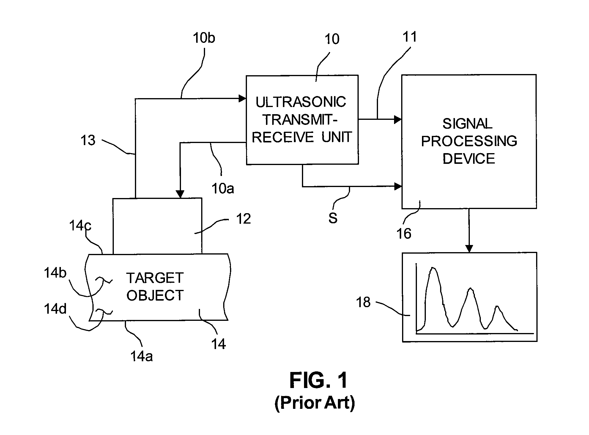
Ultrasonic detection measurement system using a tunable digital filter with 4x interpolator
a measurement system and ultrasonic technology, applied in the field of ultrasonic detection and measurement systems, can solve the problems of affecting the troubleshooting and repair of ultrasonic flaw detectors, difficult calibration, reliability, etc., and achieve the effect of increasing the perceived resolution of data
- Summary
- Abstract
- Description
- Claims
- Application Information
AI Technical Summary
Benefits of technology
Problems solved by technology
Method used
Image

Examples
first embodiment
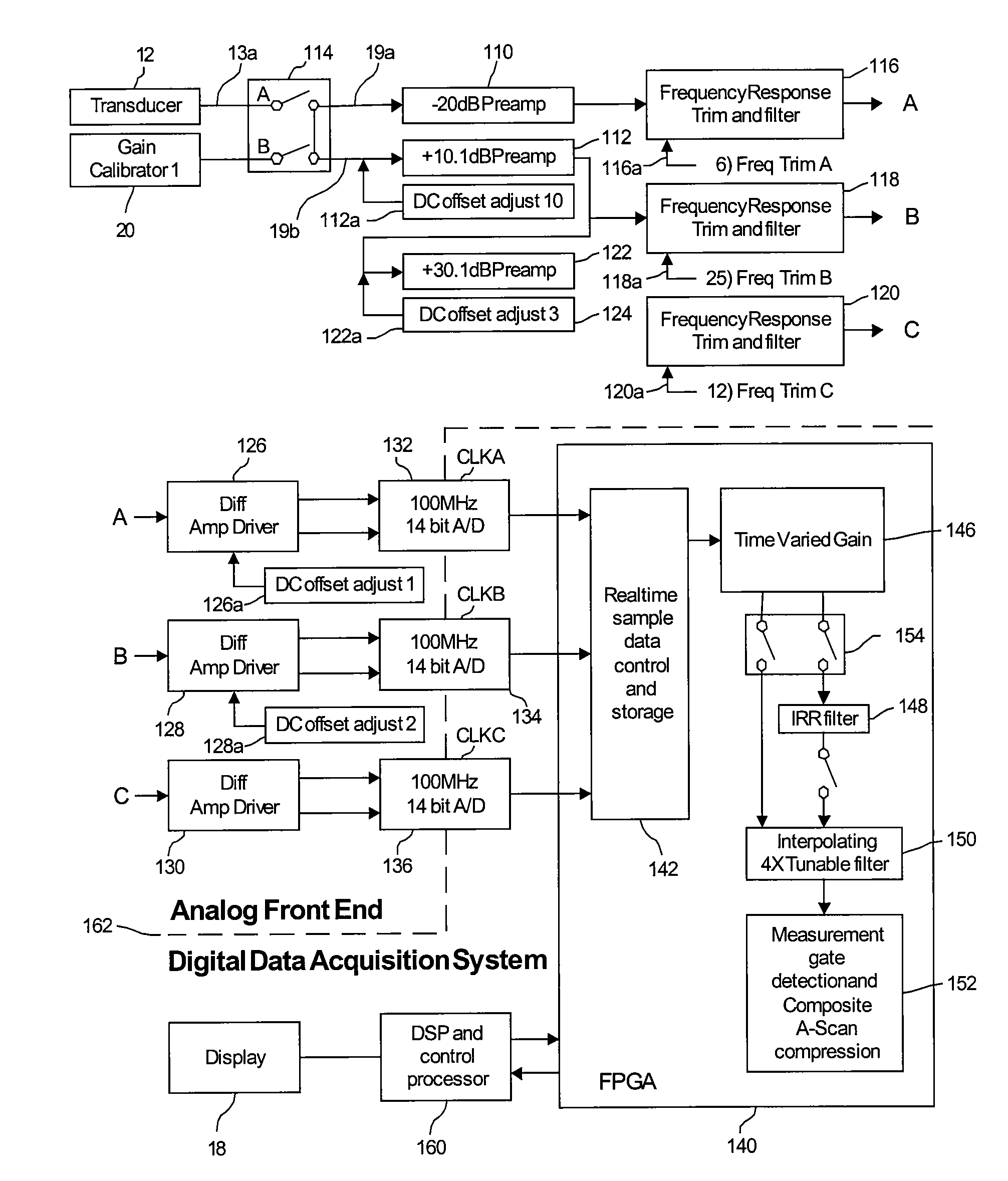
[0157]In FIG. 4b, averaging decimator 401 has same function as that of averaging decimator 206 in FIG. 4 of the first embodiment, except that its location in the signal path is different, as described earlier.
[0158]Sample DATA_IN 400 is provided to the input of averaging decimator 401 wherein the average of every pair of contiguous data samples is calculated and provided to its output. Accordingly, the effective sample rate of the output of averaging decimator 401 is one-half that of DATA_IN 400. For example, if DATA_IN 400 was 100 MS / s, the output of averaging decimator 401 would have an effective sample rate of 50 MS / s.
[0159]The MUX 402 allows either output 401a of averaging decimator 401 or DATA_IN 400 to be selected as the input provided to RAM 403. MUX 402 is controlled by AVG_DEC_EN signal 410. The RAM 403 has same function as that of RAW RAM 205 in FIG. 4 of the first embodiment.
[0160]The purpose of IIR Filter 404 is to provide high pass filtering functions that cannot be rea...
embodiment 1
[0183]BOX CAR Filter 409 has same function as that of BOX CAR Filter 209 in FIG. 4 of the Specifically, BOX CAR Filter 409 interpolates the data received from the FIR filter in a manner which increases the perceived resolution of the effective sample data by a given factor, preferably by a factor of 4
[0184]FIGS. 4c through 4h represent versions of the system shown in FIG. 4b, with, however, the multiplexers and unused sub-blocks removed. These figures are intended to simplify the explanations below of the typical operating modes. It should be noted that the inner workings of each sub-block were described earlier and need not be described again below.
1. Ultra Low Freq Narrow Band Mode [0.2 to 1.2 MHz]
[0185]Referring to FIG. 4c, DATA_IN 400 is 100 MS / s sample data provided to the input of Averaging Decimator 401 at a rate of 100 MHz. Averaging Decimator 401 reduces the effective sample rate of its input data to 50 MS / s and provides it to the input of RAM 403 at a rate of 50 MHz for s...
PUM
| Property | Measurement | Unit |
|---|---|---|
| frequency | aaaaa | aaaaa |
| excitation frequency | aaaaa | aaaaa |
| excitation frequency | aaaaa | aaaaa |
Abstract
Description
Claims
Application Information