Magnetic memory

a magnetic memory and memory technology, applied in the field of magnetic memory, can solve the problems of insufficient magnetic fields, difficult localization of magnetic fields, and inability to generate sufficient magnetic fields, so as to reduce the variations of spin-polarized current, reduce the reversal current, and reduce the effect of reversal curren

Active Publication Date: 2009-08-20
KIOXIA CORP
View PDF12 Cites 28 Cited by
  • Summary
  • Abstract
  • Description
  • Claims
  • Application Information

AI Technical Summary

Benefits of technology

[0010]An advantage of aspects of the invention is to provide a magnetic memory which is capable of reducing variations in “spin-polarized current direct driving magnetization reversals” and of achieving a reduction in the reversal current and a rapid magnetization reversal in the magnetic memory.

Problems solved by technology

However, localizing a magnetic field is difficult, because the magnetic field fundamentally spreads spatially.
This causes a problem of “cross talk”.
If a magnetic field generation source is made small to localize the magnetic field, sufficient magnetic fields cannot be generated.
The technique of the “spin-polarized current direct driving magnetization reversal” has a problem that an incomplete magnetization reversal often occurs, as a pulse width of a write-in current becomes short.
An increase in the write-in current causes a further problem about reliability, i.e., characteristics of the magnetoresistive effect element deteriorates under an influence of heat generated within the element.
In a magnetic memory using the spin-polarized current direct driving magnetization reversal method, the increase also leads to a problem being caused by miniaturizing selection transistors, i.e., by increasing memory capacity.
Then, power consumption of the magnetic memory also increases to be a problem.
In such a magnetic memory described in USPA0070047294, it is not easy to fully flow a radio-frequency (RF) current having a frequency of several GHz or more through a single bit line or word line without a ground line in order to execute a write-in for the memory, causing a big problem.

Method used


Image

  • Magnetic memory
  • Magnetic memory
  • Magnetic memory

Examples


first embodiment

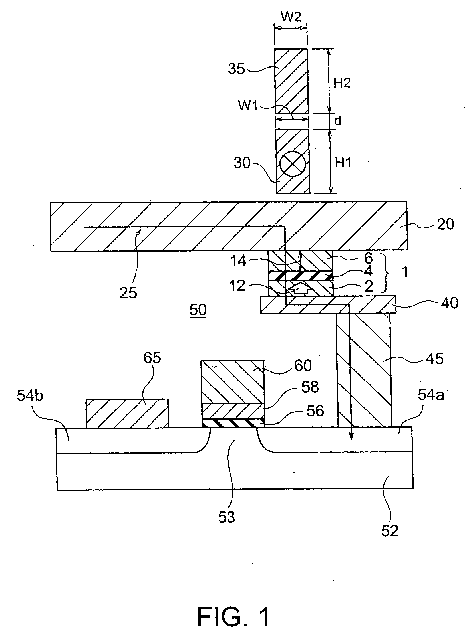
[0029]FIG. 1 is a schematic view showing a sectional structure of a magnetic memory according to a first embodiment of the invention. The magnetic memory of the embodiment is provided with a plurality of memory cells arrayed in a matrix and each cell is provided with a magnetic recording element 1, an interconnection 30 to generate a radio-frequency current-induced magnetic field, a ground line 35, an extraction electrode 40, a connecting plug 45 and a switching element 50. The interconnection to generate a radio-frequency current-induced magnetic field will be referred to as the “RF interconnection” hereinafter.

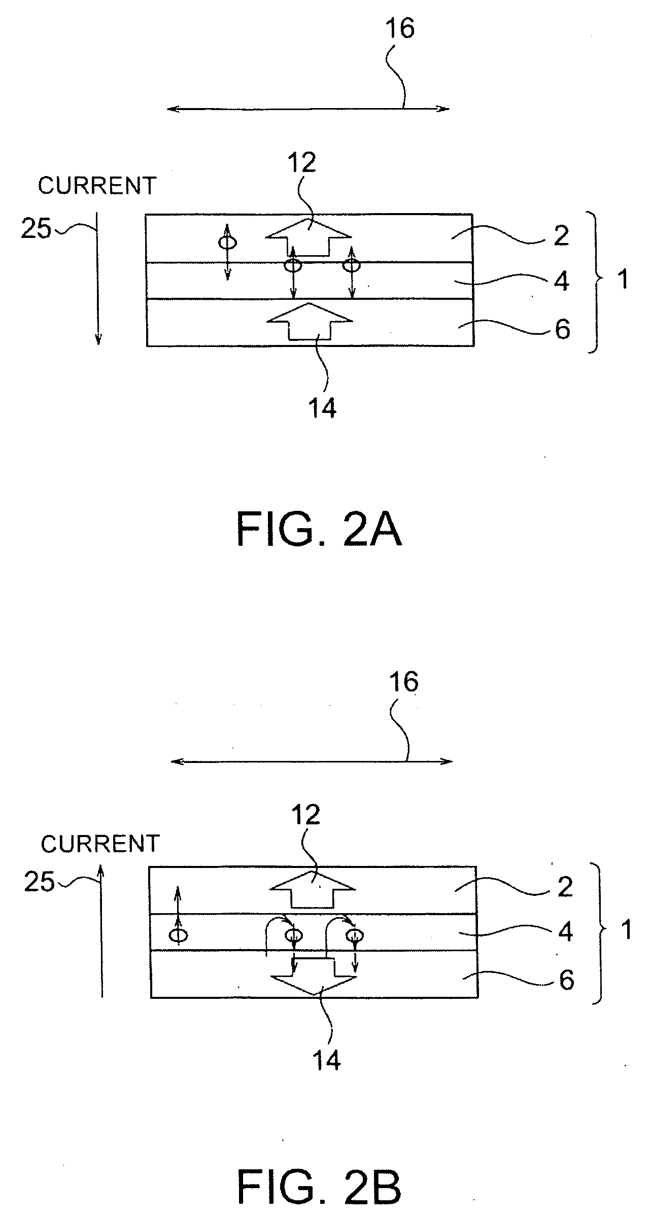
[0030]The magnetic recording element 1 is a magnetoresistive effect element and has a layered structure with a first magnetic layer 2, a first nonmagnetic layer 4, and a magnetic recording layer 6 laminated in this order. The first magnetic layer, the first nonmagnetic layer, the magnetic recording layer are referred to as the magnetic fixed layer, the nonmagnetic barrier la...

example

[0098]This embodiment will be explained more in detail with reference to an example.

[0099]In the example, the magnetic memory with the same structure as shown in FIG. 1 has been actually made (the sample number S1). The magnetic recording element of the magnetic memory is provided with the following materials and layer thicknesses. First, the magnetic fixed layer 2 is formed on the antiferromagnetic layer (not shown) consisting essentially of IrMn, and has the layered structure comprising a 1-nm thick CoFeB film / a 1-nm thick Ru film / a 4-nm thick CoFe film. The nonmagnetic barrier layer 4 comprises a 1 nm-thick MgO film. The magnetic recording layer 6 has the layered structure of a 1 nm-thick CoFe film and a 1 nm-thick CoFeB film. A CoFe film is provided at the side of the nonmagnetic barrier layer 4. The RF interconnection 30 is provided across a 0.06 μm-thick SiO2 layer above the bit line 20. The RF interconnection 30 comprises a 1-μm thick gold, and its cross-section measures 1 μm...

first modified example

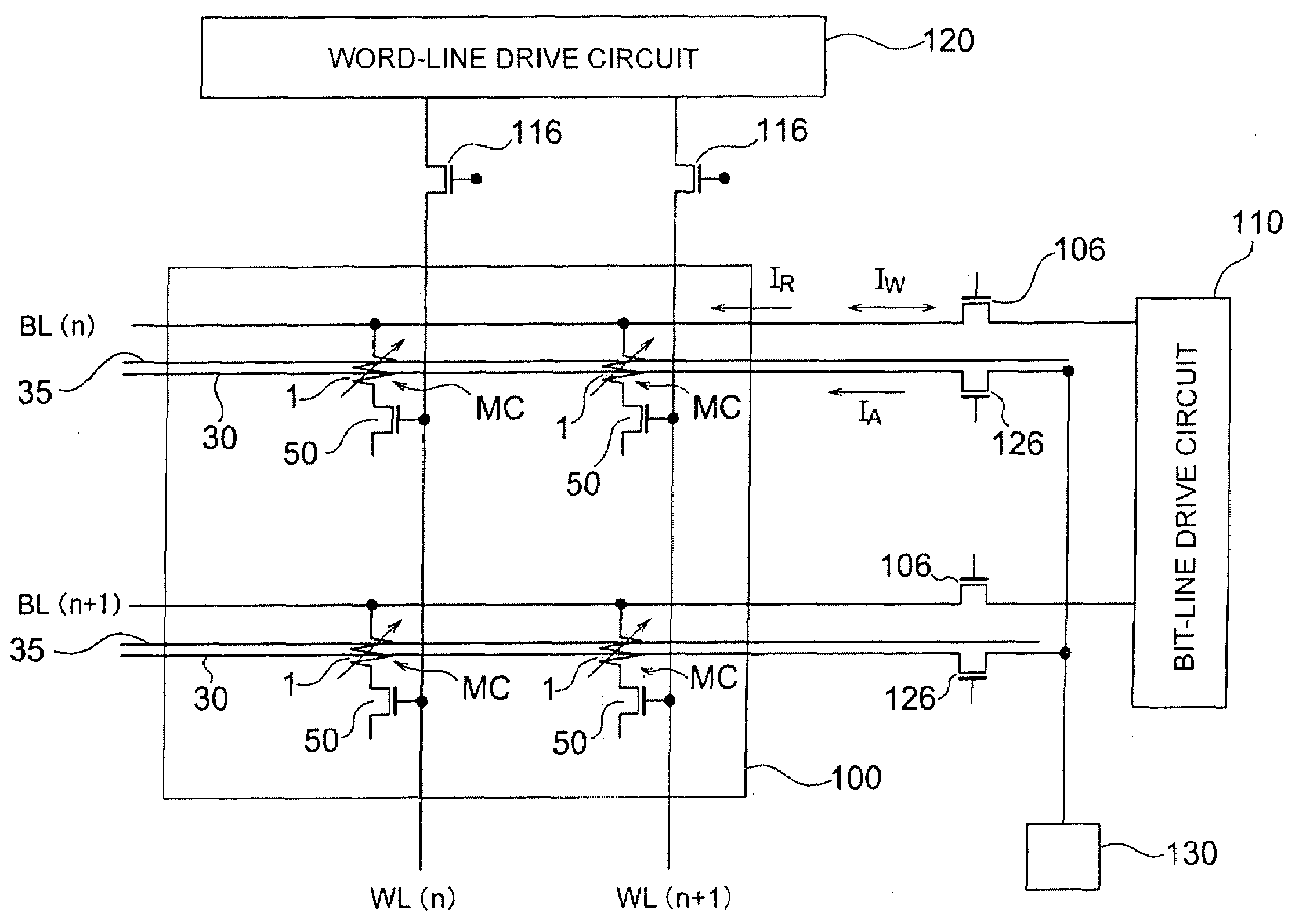
[0109]FIG. 12 shows a connection diagram of a magnetic memory according to the first modified example of the embodiment. The magnetic memory of the modified example is provided with a memory cell array 100 where a plurality of memory cells MC are arrayed in a matrix. Each memory cell MC is provided with a magnetic recording element 1 and a switching element 50 comprising an MOS transistor connected to the element 1 in series. A terminal of the magnetic recording element 1 of the memory cell MC located on the same row of the matrix is connected to the same bit line BL. Each bit line BL is connected to a bit-line drive circuit 110 via a selection element 106. In the memory cell array 100, the gate of the switching element 50 of the memory cell MC located on the same column of the matrix is connected to the same word line WL. Each word line WL is connected to a word-line drive circuit 120 via a selection element 116. And further, an RF interconnection 30 is provided in parallel to each...


PUM

PropertyMeasurementUnit
frequencyaaaaaaaaaa
magnetizationaaaaaaaaaa
nonmagneticaaaaaaaaaa

Abstract

A magnetic memory is provided with a memory cell. The memory cell includes a magnetic recording element, an interconnection to generate a radio-frequency current-induced magnetic field and a ground line. The magnetic recording element is provided with a first magnetic layer whose magnetization direction is substantially fixed, a magnetic recording layer whose magnetization direction is substantially reversed by spin-polarized electrons passing through the magnetic recording layer and a first nonmagnetic layer provided between the first magnetic layer and the magnetic recording layer. The interconnection is provided above the magnetic recording element to generate a radio-frequency current-induced magnetic field acting in a direction substantially perpendicular to a magnetization easy axis of the magnetic recording layer. The ground line is provided on a side opposite to the magnetic recording element with respect to the interconnection.

Description

CROSS REFERENCE TO RELATED APPLICATION[0001]The application is based upon and claims the benefit of priority from the prior Japanese Patent Application No. 2008-033400, filed on Feb. 14, 2008, the entire contents of which are incorporated herein by reference.FIELD OF THE INVENTION[0002]The present invention relates to a magnetic memory, more particularly to a magnetic memory whose write-in is executed by applying a radio-frequency magnetic field as a subsidiary field simultaneously with passing a normal write-in current.DESCRIPTION OF THE BACKGROUND[0003]Applying a magnetic field has been known as a method of controlling a magnetization direction of a magnetic material. In, e.g., a hard disk drive, a magnetization direction of the medium is reversed by a magnetic field generated from a magnetic head to execute a write-in. In a magnetic random access memory, a magnetization direction of a memory cell is controlled by applying a current-induced magnetic field generated by passing a cu...

Claims


Application Information

Patent Timeline
Patent Type & Authority Applications(United States)
IPC IPC(8): G11B3/70
CPCG11C11/16G11B25/04G11C11/1659G11C11/161G11C11/1675
Inventor YANAGI, SATOSHIOHSAWA, YUICHINAKAMURA, SHIHOSAIDA, DAISUKEMORISE, HIROFUMI
Owner KIOXIA CORP
Why Eureka
Try Eureka