Adsorbent and method for manufacturing the same

a technology of adsorbent and a manufacturing method, which is applied in the field of adsorbent, can solve the problems of air pollution, low hardness, and difficulty in controlling the pore diameter, and achieve the effects of easy imprégnation, shortening the immersion time, and simplifying the manufacturing method

Inactive Publication Date: 2009-08-20
NAGOYA ELECTRIC GAKUEN +1
View PDF5 Cites 48 Cited by
  • Summary
  • Abstract
  • Description
  • Claims
  • Application Information

AI Technical Summary

Benefits of technology

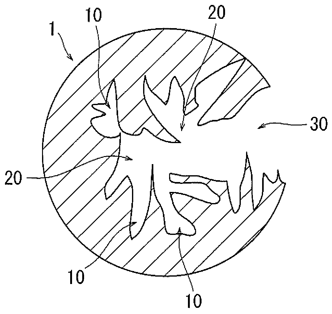
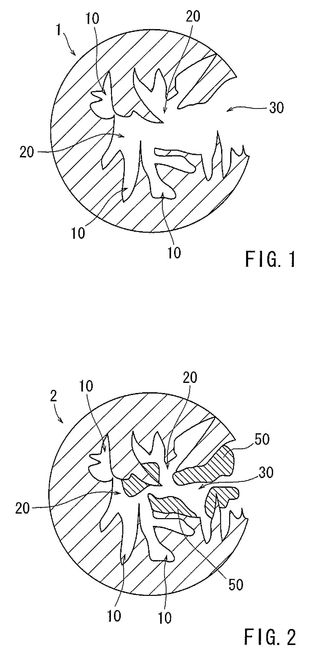
[0018]Accordingly, even the region of big pore diameter which has not directly participated in adsorption of vapor is now able to be effectively utilized as a region where vapor is able to be adsorbed. As a result, an adsorptive characteristic is also improved. Further, even if the specific surface area inherent to the activated carbon is made large, a decrease in the density of the adsorbent is suppressed by impregnation of the impregnating substance into the pores. In other words, density of the activated carbon increases due to the impregnating substance. Since the density of the activated carbon increases, heat capacity and heat conductivity are also enhanced. Incidentally, specific surface area of the activated carbon greatly affects the adsorbing amount of the vapor. In the case that the ratio of pores within a range of 1 to 10 nm is increased, the ratio of pores with a diameter about 1 to 5 nm suitable for adsorbing and desorbing vapor is also certainly increased. Accordingly, a good desorptive characteristic is also ensured while the adsorbing characteristic is effectively enhanced. In addition, since the pore region with pores slightly larger than 1 to 5 nm is also remained, vapor can easily reach the depth of the continuous pores.
[0028]It is preferred that, in the negative electrode side of the storage container used in the immersing step, an introducing pipe by which an aqueous solution of alkali metal salt of silicic acid is introduced from the outside of said storage container and a discharging pipe by which the aqueous solution in the storage container is discharged to the outside of the storage container are provided in an opposite manner. In addition, it is preferred that, in the immersing step, a water flow from the introducing pipe to the discharging pipe is formed at the negative electrode side. When a water flow which connects to inside and outside of the storage container is formed in the negative electrode side, the alkali metal ion produced by the electrolysis is discharged to the outside of the storage container. Therefore, purity of silicic acid ion in the aqueous solution increases, so that it is able to prevent impregnation of a thing unrelated to the production of silica gel into the pores and to efficiently impregnate silica gel to the activated carbon.

Problems solved by technology

However, when vapor is discharged to outer air, it causes air pollution.
In addition, when volume of the macropores is big, density of the activated carbon becomes low and hardness also lowers.
However, when various materials are merely subjected to an activating treatment, control of the pore diameter is difficult and it is almost impossible to prepare an activated carbon having a uniform pore diameter.
Further, although improvements mostly in an increase of specific surface area have been investigated, such improvements do not directly contribute in a high efficiency because a decrease in density of the adsorbent as a result of an increase in the specific surface area does not allow an increase in the adsorptive property based on the volume.
On the other hand, although the micropores have a high adsorptive characteristic, there is a problem in terms of desorptive characteristic when there are too many pores where the pore diameter is less than about 1 nm.
Accordingly, in the case that the micropores where the pore diameter is less than about 1 nm is too many, there is also a problem in terms of adsorptive and desorptive characteristics which are demanded for an adsorptive material for gasoline vapor.
Thus, many pores having big pore diameter which are useless in terms of an adsorptive function still remain therein.
However, it is not a direct object therein to make the mesopores and the macropores narrow and small.
In addition, a problem of de-dissolving of the vapor dissolved in the organic compound remains as well.
Further, although silica gel is used as an adsorptive material, silica gel is less effective adsorptive amount than activated carbon.
Furthermore, there is also a limitation in increase of adsorbed amount by dissolving in an organic compound.
In the diffusing impregnation as such, the impregnating speed is slow and long time is needed for impregnating deeply into the pores (to the inner part).
Consequently, the pore diameter is not within the range of the pore diameter which is appropriate for adsorption and desorption of gasoline vapor so that said adsorptive material is unable to be used as an adsorptive material for a canister.
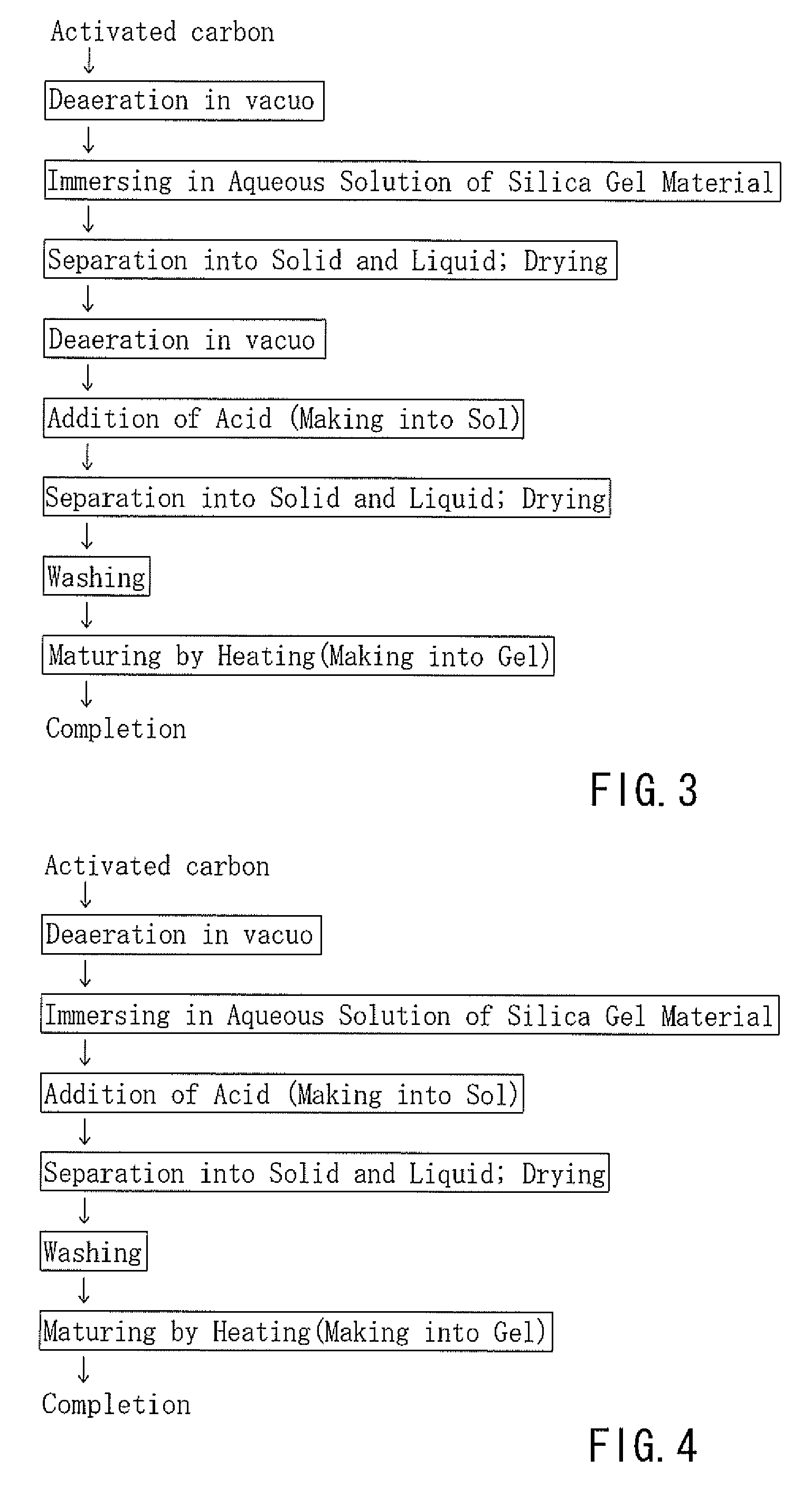
However, in the case that silica gel material is impregnated into the pores of the powdery activated carbon and the resulting compounded activated carbon is further made into a granular adsorbent using a binder, both the impregnating and molding steps are necessary and thus the manufacture is complicated.
Further, in the granular adsorbent, there is a problem that the pore inlet of each powdery adsorbent is clogged by a binder.
However, it is not possible to impregnate silica into the inner area of the pores of each powdery activated carbon.

Method used


Image

  • Adsorbent and method for manufacturing the same
  • Adsorbent and method for manufacturing the same
  • Adsorbent and method for manufacturing the same

Examples


modified embodiment

[0104]In the above-mentioned third manufacturing method, the positive electrode 111 is provided separately from the activated carbon 1. However, the embodiment is not limited thereto, the activated carbon itself may be made into a positive electrode. For example, a conductive wire may be directly connected to a product where activated carbon particles are made into granules in a predetermined shape or to the activated carbon in a predetermined shape. When the activated carbon (which is in a predetermined shape or is made into granules of a predetermine shape) is used as the positive electrode, the frame wall 115 is not necessary. Alternatively, a conductive wire may be directly connected to the activated carbon filled in a housing container.

[0105]In the third manufacturing method, although the electrodes 111, 112 and the water flow are provided in a longitudinal direction, as shown in FIG. 8, the electrodes 111, 112 and the water flow may also be provided in a transverse direction. ...

examples

[0110]

[0111]BAX 1500 (activated carbon A), which is a wood-type activated carbon activated with phosphoric acid, of Mead Westvaco and granular Shirasagi KL (activated carbon B), which is a wood-type activated carbon activated by KOH, of Nippon Enviro Chemicals, were used as activated carbons. The pore diameter distributions of the activated carbon A and the activated carbon B are shown in FIG. 13, and various physical properties of the activated carbon A and the activated carbon B are shown in Table 3. It is apparent from FIG. 13 that many mesopores are present in both of the activated carbon A and the activated carbon B. It is also noted from Table 3 that micropore volume is bigger in the activated carbon A than in the activated carbon B. Specific surface area was measured by an N2 adsorption method and a filling density was measured by a particle filling method. In both of the activated carbon A and the activated carbon B, a particle size was limited within the range between 0.075...


PUM

PropertyMeasurementUnit
pore size ratioaaaaaaaaaa
pore diameteraaaaaaaaaa
pore sizeaaaaaaaaaa

Abstract

Silica gel is impregnated as an impregnating substance into pores of an activated carbon having mesopores and macropores. Since the mesopores and the macropores are impregnated with the silica gel, they are made narrow and small whereby a pore size ratio within a range of 1 to 10 nm is increased.

Description

[0001]This application claims priority to Japanese patent application serial numbers 2008-035800, 2008-327730 and 2008-318151, the contents of which are incorporated herein by reference.BACKGROUND OF THE INVENTION[0002]1. Field of the Invention[0003]The present invention relates to an adsorbent where an impregnating substance is impregnated into pores whereby adsorptive characteristic and desorptive characteristic to evaporated fuel (which is called as “vapor” hereinafter) generated from gasoline are excellent and also relates to a method for manufacturing the adsorbent.[0004]2. Description of the Related Art[0005]In a fuel tank of automobiles, gasoline is evaporated to generate vapor. The evaporated amount increases when temperature of the inner area of the fuel tank becomes high due to outer temperature during stopping or due to gasoline combustion during running. An automobile has a function for discharging the gas in the fuel tank to outer air in order to control the inner press...

Claims


Application Information

Patent Timeline
Patent Type & Authority Applications(United States)
IPC IPC(8): B01J20/10B01J20/20
CPCB01J20/103B01J20/3234B01J20/28057B01J20/28083B01J20/28085B01J20/28097C01B31/083C01B31/085C01B33/14C01B33/142C01B33/143F02M25/0854B01J20/28069B01J20/3204B01J20/20C01B32/354C01B32/306
Inventor WATANABE, FUJIOHASATANI, MASANOBUMAKINO, KATSUHIKOOGITA, TAMOTSU
Owner NAGOYA ELECTRIC GAKUEN
Why Eureka
Try Eureka