Method for Reducing Fouling in Furnaces

a technology of additives and furnaces, applied in the field of additives, can solve the problems of increased energy costs, increased energy costs, and the surface of the tubes in the heat exchanger may be exposed to extreme heat, and achieve the effect of reducing the fouling of the heat exchanger

Active Publication Date: 2009-08-27
BAKER HUGHES INC
View PDF7 Cites 10 Cited by
  • Summary
  • Abstract
  • Description
  • Claims
  • Application Information

AI Technical Summary

Benefits of technology

[0008]In one aspect, the invention is a process for reducing heat exchanger fouling in an organic chemical production process comprising adding to an organic chemical production process stream an antifoulant additive wherein the antifou

Problems solved by technology

The tubes in a heat exchanger may be exposed to extreme heat.
In either case, the one element that the process streams have in common is that the passing of a feed material through a flow path that is subject to heat from a burner or other heat source can result in the fouling of the surfaces of the tubes and/or production of undesirable materials within the proc

Method used


Image

  • Method for Reducing Fouling in Furnaces
  • Method for Reducing Fouling in Furnaces
  • Method for Reducing Fouling in Furnaces

Examples


examples

[0037]The following examples and hypothetical example are provided to illustrate the invention. The examples are not intended to limit the scope of the invention and they should not be so interpreted. Amounts are in weight parts or weight percentages unless otherwise indicated.

example ii

Hypothetical Example II

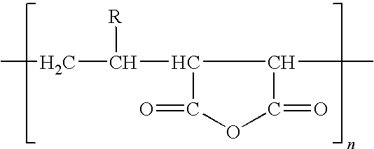
[0039]An antifoulant additive of the invention having two components, where a first component is a magnesium overbase (MO) and the second component is a maleic anhydride alpha olefin copolymer (CP), is used to treat the pyrolysis unit described in the hypothetical comparative example. The ratio of CP:MO 1:2 and the antifoulant additive is fed at a rate of 800 ppm by with into the feed stream using two drums each having its own pump, the effluent from the pump going through a static mixer, and the antifoulant additive being fed into the process stream just prior to process stream entering the furnace. The average time between cleanings for the 4 heat exchangers is 66 days.

example 1

[0040]Several 50 ml samples of EDC feed is added to pre-weighed 150 mL Ace Glass slit vented covered reactor liners. Additives were included into each sample as shown below in the Table. Each compound was added as the specified number of microliters of a solution having a concentration of each agent also shown in the table. The reactor liner is placed into a reactor. An overhead (clean) reaction vessel / transfer line is tared and secured to the test reactor.

[0041]The furnace is heated to a range of from about 890° F. to 950° F. (476° C. to 510° C.). The reactor is then placed into the heated furnace. An automated computer based test program records the test elapsed time, sample temperature and autoclave pressure every 30 seconds throughout the test run. The test apparatus is fitted with a 0-1000 psi (0-6.9 MPa) pressure transducer and thermocouples to record test fluid, reactor heater, and reactor chamber / transfer line temperatures. Elapsed time is recorded and at a preset time the r...


PUM


Abstract

Heat exchanger fouling in organic chemical production processes may be reduced using an antifoulant additive. The antifoulant additive may have one component selected from the group consisting of an alkylphosphate ester, and an alpha olefin maleic anhydride copolymer; or it may have two components selected from the group consisting of a metallic overbase, an alkylphosphate ester, and an alpha olefin maleic anhydride copolymer, wherein at least one of the two components in not an overbase. An additive having three components: a metallic overbase, an alkylphosphate ester, and an alpha olefin maleic anhydride copolymer; is also within the scope of the disclosure. The abstract is submitted with the understanding that it will not be used to interpret or limit the scope or meaning of the claims. 37 CFR 1.72(b)

Description

CROSS REFERENCE TO RELATED APPLICATIONS [0001]This application claims priority from the U.S. Provisional Patent Application having the Ser. No. 61 / 031,237; which was filed on Feb. 25, 2008; and which is fully incorporated herein by reference.BACKGROUND OF THE INVENTION[0002]1. Field of the Invention[0003]The invention relates to additives useful for reducing fouling in furnaces. The invention particularly relates to additives useful for reducing fouling in furnaces used for producing organic chemicals.[0004]2. Background of the Art[0005]Chemical plants producing organic chemicals often use furnaces to heat process streams. Whether heated with steam or heat transfer fluids, or directly using burners, such furnaces function by heating tubes through which process fluids are passing. The furnaces include a number of such tubes, generally arranged vertically, that form a continuous flow path, or coil, through the furnace. These tubes are generally in a unit referred to in the art as a he...

Claims


Application Information

Patent Timeline
IPC IPC(8): C10G9/16C02F5/14
CPCC02F5/08C02F2103/36C10G2300/80C10G75/04C10G2300/4075C10G9/16
Inventor STARK, JOSEPH L.SPAGNUOLO, LORENZOMETZLER, ROGER D.FALKLER, THOMAS J.
Owner BAKER HUGHES INC
Why Eureka
Try Eureka